Installation, Alternate wiring diagram for wall switch – Regency Zero Clearance Direct Vent Gas Fireplace P36-LP4 User Manual
Page 45
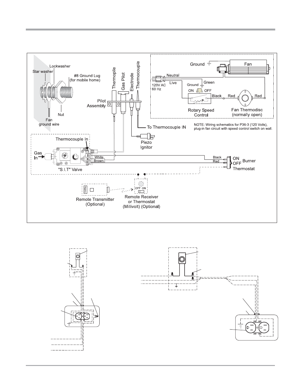
FPI P36-4 Zero Clearance Direct Vent Gas Fireplace
45
P36 Electrical C onnection A lternative Schem e "A ",
Pow er at Stove
W all Junction Box
*Speed C ontrol
Sw itch w ith
lead w ires
(R egency)
W ire N uts
W ire N uts
14 AW G w ire
14 AW G w ire
*W ire C lam p
*R eceptacle Box
inside stove
*R eceptacle
(dedicated use
by stove fan only)
120 Volts
60 H z
C opper G round
W hite (N eutral)
Black (H ot)
~
P36 Electrical C onnection A lternative Schem e "B ",
Pow er at Sw itch
W all Junction Box
*Speed C ontrol
Sw itch w ith lead w ires
W ire N uts
14 AW G w i
re
*W ire C lam p
120 Volts
60 H z
C opper G round
W hite (N eutral)
Black (H ot)
W ire
Black
W hite
G round
*R eceptacle Box
inside stove
~
*R eceptacle
(dedicated use
by stove fan only)
* = supplied w ith fan kit
O ther parts are to be supplied
by electrician or installer
ALTERNATE WIRING DIAGRAM FOR WALL SWITCH
INSTALLATION