Roberts Gorden GordonRay BH-175 User Manual
Page 8
ROBERTS GORDON
®
BH- S
ERI E S
S
UBM IT TAL
S
HE E T
© 2004 Roberts-Gordon
BEFORE IN ST AL LATI ON AND OPER ATI ON OF HEATI NG E QUIPMENT, READ AND U NDERSTAND T HE INSTALL AT ION, OPERATIO N AND SERVICE MANUAL .
APPL ICATION S, ENGI NEE RING AND DET AI LE D GUID ANCE ON SYST EMS DE SIGN, INSTAL LATI ON AND PRODUCT PE RFORMANCE IS AVAI LABLE UPON RE QUEST. ROBERT S GORDON
®
PRODUCT S ARE T O BE
INSTAL LE D ONL Y IN ACCORDANCE WI TH L OCAL L AWS, CODES AND REGUL AT IONS, AND ONLY BY A CONT RACT OR QUALI FIE D I N THE I NST ALL AT ION AND SE RVICE OF GAS-FIRE D HE AT ING EQUI PME NT.
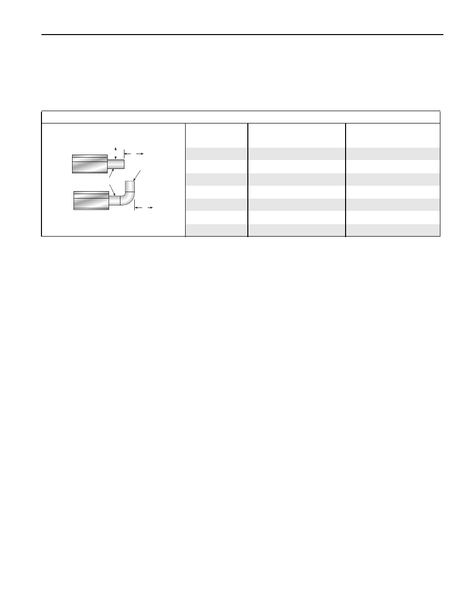
NOTE: 1. All dimensions are from the surfaces of all tubes, couplings and elbows.
2. Clearances B, C and D can be reduced by 50% after 25' (7.5 m) of tubing downstream
from where the burner and burner tube connect.
3. “-” indicates an unapproved application. Roberts-Gordon prohibits the installation of
this heater for all unapproved applications.
Venting
(inches)
(centimeters)
Model
A
E
F
A
E
F
BH-40
14
18
18
36
46
46
BH-60
14
18
18
36
46
46
BH-80
20
24
18
51
61
46
BH-100
20
24
18
51
61
46
BH-115/125
20
24
18
51
61
46
BH-140/150
20
30
18
51
77
46
BH-175/200
20
30
18
51
77
46
Infrared Tubes
Vent
Pipes
Unvented
Vented
A
E
F