2" (5 cm), 2004 roberts-gordon, Coupling and tube assembly (continued) – Roberts Gorden GordonRay BH-175 User Manual
Page 15: Repeat a - d until all tubes are assembled
ROBERTS GOR DON
®
BH- S
ERI E S
S
UBM IT TAL
S
HE E T
© 2004 Roberts-Gordon
BEFORE IN ST AL LATI ON AND OPER ATI ON OF HEATI NG E QUIPMENT, READ AND U NDERSTAND T HE INSTALL AT ION, OPERATIO N AND SERVICE MANUAL .
APPL ICATION S, ENGI NEE RING AND DET AI LE D GUID ANCE ON SYST EMS DE SIGN, INSTAL LATI ON AND PRODUCT PE RFORMANCE IS AVAI LABLE UPON RE QUEST. ROBERT S GORDON
®
PRODUCT S ARE T O BE
INSTAL LE D ONL Y IN ACCORDANCE WI TH L OCAL L AWS, CODES AND REGUL AT IONS, AND ONLY BY A CONT RACT OR QUALI FIE D I N THE I NST ALL AT ION AND SE RVICE OF GAS-FIRE D HE AT ING EQUI PME NT.
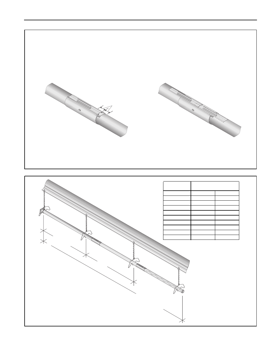
Coupling and Tube Assembly (Continued)
Coupling and Tube Assembly (Continued)
Incorrect Slide Bar
position
Correct Slide Bar
dimensions
± 2" (5 cm)
Drive Slide Bar until tight.
End of Slide Bar should be
within tolerance listed below.
• Repeat A - D until all tubes are assembled.
Tighten slide bar as shown below
10' ± 1'
(305 cm ± 25 cm)
Total Overall
Tube Length
7' 6" ± 1'
(229 cm ± 25 cm)
Model
Tube Length
Minimum Maxi mum
BH-40
10’ (3 m)
10’ (3 m)
BH-60
20’ (6 m)
20’ (6 m)
BH-80
20’ (6 m)
30’ (9 m)
BH-100
30’ (9 m)
40’ (12 m)
BH-115
30’ (9 m)
50’ (15 m)
BH-125
40’ (12 m)
50’ (15 m)
BH-140
40’ (12 m)
60’ (18 m)
BH-150
50’ (15 m)
60’ (18 m)
BH-175
50’ (15 m)
70’ (21 m)
BH-200
60’ (18 m)
80’ (24 m)