2004 roberts-gordon, Bh-series u-tube layout overviews legend – Roberts Gorden GordonRay BH-175 User Manual
Page 20
ROBERTS GORDON
®
BH- S
ERI E S
S
UBM IT TAL
S
HE E T
© 2004 Roberts-Gordon
BEFORE IN ST AL LATI ON AND OPER ATI ON OF HEATI NG E QUIPMENT, READ AND U NDERSTAND T HE INSTALL AT ION, OPERATIO N AND SERVICE MANUAL .
APPL ICATION S, ENGI NEE RING AND DET AI LE D GUID ANCE ON SYST EMS DE SIGN, INSTAL LATI ON AND PRODUCT PE RFORMANCE IS AVAI LABLE UPON RE QUEST. ROBERT S GORDON
®
PRODUCT S ARE T O BE
INSTAL LE D ONL Y IN ACCORDANCE WI TH L OCAL L AWS, CODES AND REGUL AT IONS, AND ONLY BY A CONT RACT OR QUALI FIE D I N THE I NST ALL AT ION AND SE RVICE OF GAS-FIRE D HE AT ING EQUI PME NT.
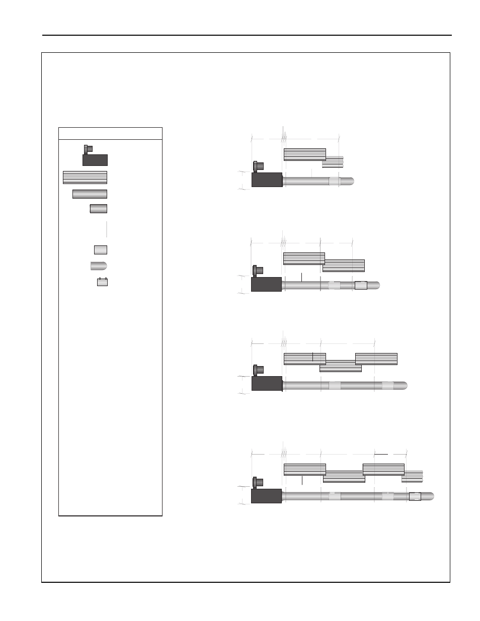
BH-Series U-Tube Layout Overviews
LEGEND
a = 14" (36 cm)
reflector width (not shown)
b = 2" (5 cm)
end cap to burner
c = 2" (5 cm)
end cap to hanger
d = 7'6" (229 cm)
distance first hanger
e = 10' (305 cm)
distance between hangers
f = 5' (153 cm)
distance between last full tube
hanger and half tube hanger
g = 12.5" (32 cm) burner length
h = 11" (28 cm) burner height
* Require the last reflector
before the U-Tube to be cut in
half for use on both sides.
** Require the last tube before
the U-Tube to be cut in half for
use on both sides.
U-Tube
Burner
Reflector
Tube 10'
Tube/Reflector
Hanger
Coupling
Assembly
Tube 5' **
c
b
d
e
g
h
40' Tube Length
c
b
d
f
g
h
30' Tube Length**
20' Tube Length*
BH-80
BH-100
BH-115
BH-60
BH-80
BH-100
BH-115
BH-125
BH-140
g
c
b
h
e
BH-115
BH-125
BH-140
BH-150
BH-175
c
b
d
e
f
g
h
50' Tube Length* **
Vent Adapter
(not shown)