Roberts Gorden GordonRay BH-175 User Manual
Page 6
ROBERTS GORDON
®
BH- S
ERI E S
S
UBM IT TAL
S
HE E T
© 2004 Roberts-Gordon
BEFORE IN ST AL LATI ON AND OPER ATI ON OF HEATI NG E QUIPMENT, READ AND U NDERSTAND T HE INSTALL AT ION, OPERATIO N AND SERVICE MANUAL .
APPL ICATION S, ENGI NEE RING AND DET AI LE D GUID ANCE ON SYST EMS DE SIGN, INSTAL LATI ON AND PRODUCT PE RFORMANCE IS AVAI LABLE UPON RE QUEST. ROBERT S GORDON
®
PRODUCT S ARE T O BE
INSTAL LE D ONL Y IN ACCORDANCE WI TH L OCAL L AWS, CODES AND REGUL AT IONS, AND ONLY BY A CONT RACT OR QUALI FIE D I N THE I NST ALL AT ION AND SE RVICE OF GAS-FIRE D HE AT ING EQUI PME NT.
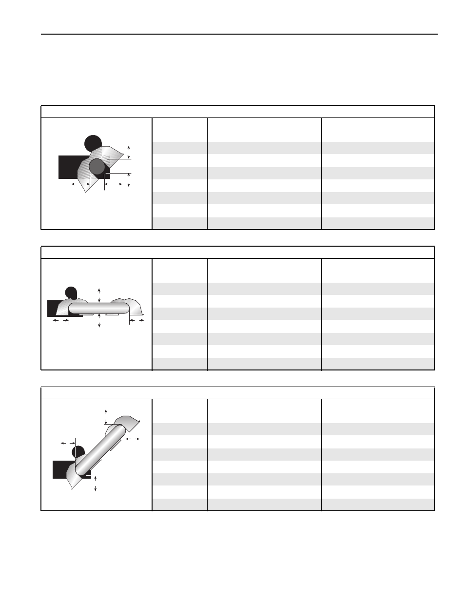
NOTE: 1. All dimensions are from the surfaces of all tubes, couplings and elbows.
2. Clearances B, C and D can be reduced by 50% after 25' (7.5 m) of tubing
downstream from where the burner and burner tube connect.
3. “-” indicates an unapproved application. Roberts-Gordon prohibits the installation
of this heater for all unapproved applications.
45° Tilt Reflector
(inches)
(centimeters)
Model
A
B
C
D
A
B
C
D
BH-40
8
8
50
46
21
21
127
117
BH-60
8
8
59
54
21
21
150
138
BH-80
8
8
65
60
21
21
166
153
BH-100
10
8
73
64
26
21
186
163
BH-115/125
10
8
77
69
26
21
196
176
BH-140/150
12
8
83
74
31
21
211
188
BH-175/200
12
8
85
79
31
21
216
201
C
B
D
A
U-Tube, Standard Reflector
(inches)
(centimeters)
Model
A
B
C
D
A
B
C
D
BH-40
-
-
-
-
-
-
-
-
BH-60
6
35
62
30
16
89
158
77
BH-80
6
38
68
37
16
97
173
94
BH-100
6
40
75
39
16
102
191
100
BH-115/125
6
46
78
43
16
117
199
110
BH-140/150
6
50
83
47
16
127
211
120
BH-175/200
8
54
87
51
21
138
221
130
B
D
C
A
U-Tube, Full 45°
(inches)
(centimeters)
Model
A
B
C
D
A
B
C
D
BH-40
-
-
-
-
-
-
-
-
BH-60
8
8
59
42
21
21
150
107
BH-80
8
8
65
46
21
21
166
117
BH-100
8
8
73
52
21
21
186
133
BH-115/125
8
8
77
61
21
21
196
155
BH-140/150
8
8
83
66
21
21
211
168
BH-175/200
8
8
85
70
21
21
216
178
C
D
B
A