Precautions to be taken when debugging, 1 reset, 2 system clock – Renesas M34502T-MCU User Manual
Page 27: 3 real-time capability of timer
( 25 / 38 )
5. Precautions to Be Taken When Debugging
5.1 Reset
The M34502T-MCU uses a 74AC14 for its RESET signal input buffer, so that its electrical
characteristics differ from those of an actual MCU. Table 5.1 lists the RESET signal input
characteristics of the M34502T-MCU.
Table 5.1 RESET signal input characteristics
5.2 System Clock
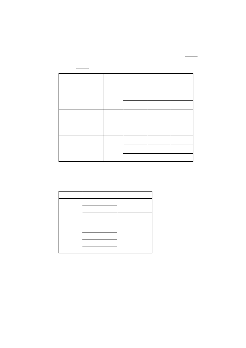
Depending on the supply voltage and operation modes, use one of the frequencies listed in Table 5.2.
Table 5.2 Operating frequencies of M34502T-MCU
To change this clock frequency to suit that of the target system, attach the necessary parts to oscillator
circuit board OSC-2 (included).
For details about the oscillation circuit constant, consult your oscillator manufacturer.
5.3 Real-time Capability of Timer
The PC4504 and M34502T-MCU have their internal clock operating even during emulation, so that
the timer values keep changing.
Example:
(1) When single-stepping the program
(2) When registers or internal RAM are referenced or modified
Mode
Default
Low-speed
Medium-speed
High-speed
Default
Low-speed
Medium-speed
High-speed
Voltage
3 V
5 V
Frequency
4.4 MHz or less
3.0 MHz or less
1.5 MHz or less
4.4 MHz or less
H-level threshold voltage
L-level threshold voltage
Hysteresis voltage
Item
Symbol
V
P
V
N
V
H
Voltage (V
CC
)
3.0 V
4.5 V
5.5 V
3.0 V
4.5 V
5.5 V
3.0 V
4.5 V
5.5 V
Max.
2.2 V
3.2 V
3.9 V
-
-
-
1.2 V
1.4 V
1.6 V
Min.
-
-
-
0.5 V
0.9 V
1.1 V
0.3 V
0.4 V
0.5 V