7 led – Renesas M34502T-MCU User Manual
Page 25
( 23 / 38 )
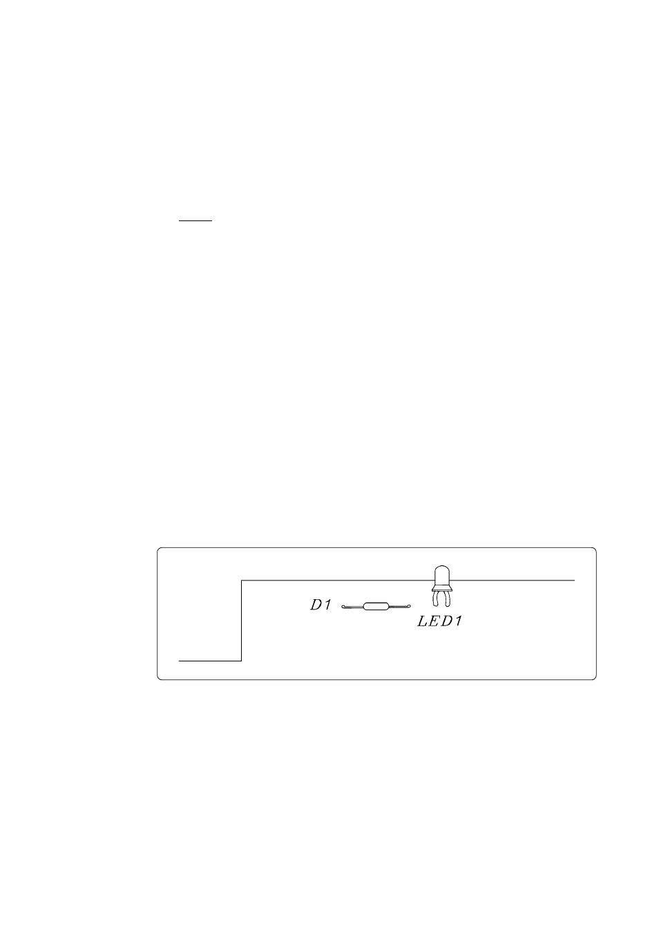
Figure 4.12 Layout of the LED
Some signals connected to the target system are emulated on the M34502T-MCU. For details, see
"6. Connection Circuit Diagram of the M34502T-MCU".
(1) Pins connected directly to the target system (2 types, 3 lines)
• P3
0
, P3
1
*
1
• V
SS
(2) Pins connected to the target system via emulation circuits and other devices. (6 types, 18 lines)
• P0
0
to P0
3
• P1
0
to P1
3
• P2
0
, P2
1
• D
0
to D
5
*
2
• RESET
• EV
DD
*
3
(3) Pins not connected to the target system (3 types, 3 lines)
• X
IN
*
4
• X
OUT
• CNV
SS
*1 For 4501, 4506 and 4580 Group MCUs, the ports P3
0
and P3
1
are not connected to the target
system when the M34501T-PTC is mounted.
*2 For 4501, 4506 and 4580 Group MCUs, the ports D
4
and D
5
are not connected to the target system
when the M34501T-PTC is mounted.
*3 EV
DD
does not input the power supply from the target system, but outputs it to the target system
from the power circuit on the M34502T-MCU. The output (ON/OFF) and the power supply (3
V/5 V) of EV
DD
are changed by the switches SW1 and SW3 respectively.
*4 X
IN
is input from oscillator circuit board OSC-2 on the M34502T-MCU and cannot be input from
the oscillator circuit on the target system. To change the frequency of the system clock, use
oscillator circuit board OSC-2 (included) with other necessary parts mounted.
4.7 LED
Figure 4.12 shows the LED layout of the M34502T-MCU. The LED lights in green when the power
is supplied.