Renesas M34502T-MCU User Manual
Page 23
( 21 / 38 )
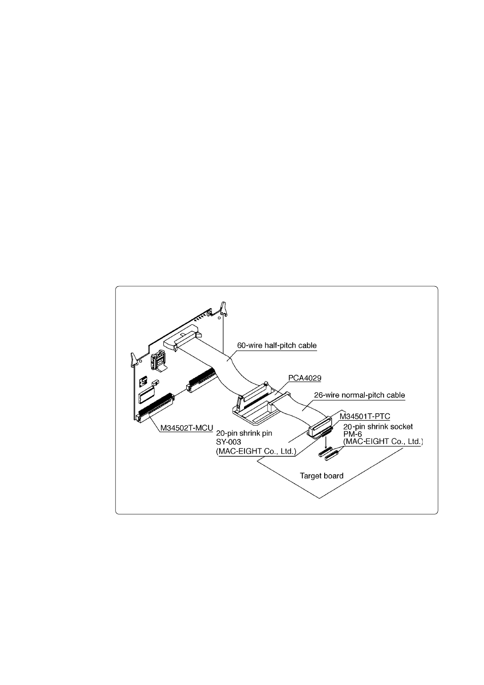
Figure 4.10 Connecting to an IC socket for 20-pin SDIP
(2) For 4501, 4506 and 4580 Groups
How to connect the M34502T-MCU to the target system when using for 4501, 4506 and 4580
Groups is shown below.
Make note of the fact that it is not possible to connect the M34502T-MCU directly to the foot
pattern of the MCU package (20P2N-A).
a. Connecting to the IC Socket for 20-pin SDIP on the Target System
Attach the 26-wire normal-pitch cable (included) to pitch converter board M34501T-PTC to
connect the M34501T-MCU board with the IC socket for 20-pin SDIP on the target system.
Figure 4.10 shows the connection to the target system using the M34501T-PTC. And Figure
4.11 shows the pin assignments of the M34501T-PTC. The following products are required for
connection to the target system.
• 60-wire half-pitch cable (40 cm)
• Pitch converter board PCA4029
• 26-wire normal-pitch cable (10 cm)
• Pitch converter board M34501T-PTC
Table 4.9 lists the connector signal assignments of pitch converter board M34501T-PTC. The
pin assignments of the M34501T-PTC is the same as for the 20SDIP of the 4501 and 4506
Groups. When connecting pitch converter board M34501T-PTC, check the No. 1 pin positions
of the cable and the connector.
To avoid damage to the emulator and target system, be careful of the connection.