2 dhd controller front panel, Figure 2-4 . dhd controller front panel, Dhd controller front panel – Runco VISTAGE V-50HD User Manual
Page 21: 4. dhd controller front panel, Pre l iminar y
Vistage™ Series Flat-Panel Display Installation/Operation Manual
7
PRE
L
IMINAR
Y
The rear-panel connectors reside behind protective cover plates with cable routing slots.
Use a Phillips screwdriver to remove the plates in order to connect cables, and to
re-attach them afterward.
1.
AC POWER INPUT
Connect the V-50HD/V-63HD to AC power here.
2.
DHD INPUT PANEL
• SECONDARY INPUT
For future use.
• SERVICE PORT
For future use.
• PRIMARY INPUT
HDCP-compliant digital video input. Connect the HDMI output from the DHD
Controller to this input.
2.2
DHD Controller Front
Panel
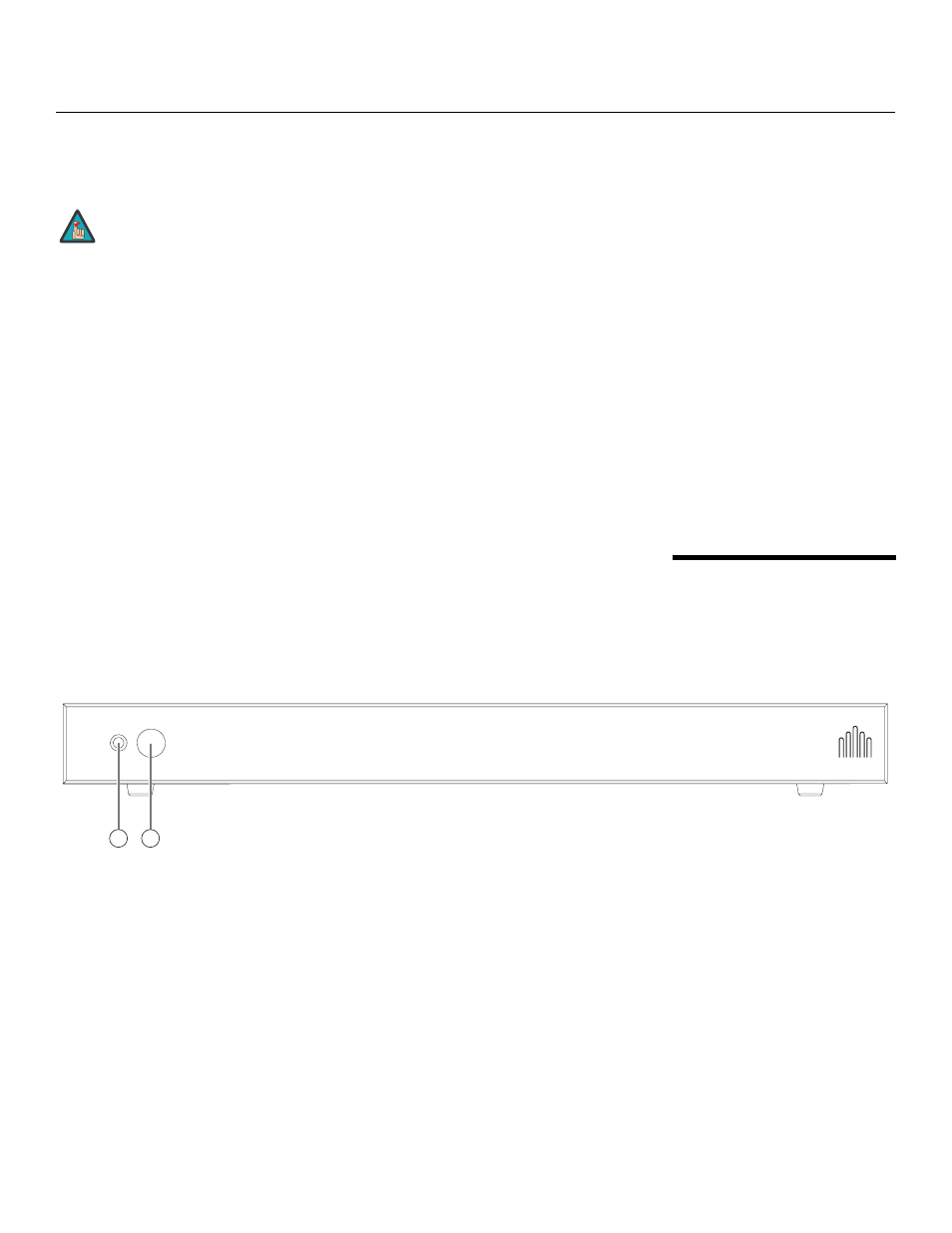
Figure 2-4 shows the controls and indicators on the DHD Controller front panel; the
paragraphs that follow describe them.
Figure 2-4. DHD Controller Front Panel
1.
STATUS LED
Indicates DHD Controller status as follows:
• Solid yellow = DHD Controller is in standby mode (off)
• Flashing blue = DHD Controller is starting up
• Solid blue = normal operation
• Off = DHD Controller is shutting down (“cool-down” mode)
• Flashing yellow = error condition
• Alternately flashing blue/yellow = firmware upgrade in progress
2.
REMOTE CONTROL SENSOR
Receives the signals from the remote control.
To minimize the amount of space required behind the panel when
wall-mounted, the connectors are recessed and right-angled
relative to the rear panel surface (the AC input faces right and the
other input connectors face downward).
Note
1
2