Assembling the dp90/dp90s, Assembling, Check the parts – Roland DP90 User Manual
Page 54: When moving the unit
&
&
Assembling
*
5
1
0
0
0
2
8
3
8
0
-
0
2
*
Assembling the DP90/DP90S
* To ensure that you assemble this unit correctly, please read this manual carefully
before you begin assembly. Keep this manual nearby for reference when needed.
* Keep this unit horizontal when lifting it during assembly or transport.
* Be careful not to pinch your hands or drop this unit on your foot during assembly or
transport.
* You must obtain the assistance of at least one additional person when assembling or
transporting this unit.
* Keep small parts such as screws, stabilizers, and cord clamps out of the reach of small
children to ensure that these items are not swallowed accidentally.
* The screwdriver needed for assembly is not included. You’ll need have a Phillips
screwdriver on hand.
* Hand-tighten the screws fi rst, and then tighten them fi rmly. Start by tightening the
screws until they are approximately half hidden. Do not use a power screwdriver
when tightening the screws to their fi nal position. Doing so may strip the threads.
* Tighten the screws fi rmly, and place the unit at a location that is level and sure to
remain stable. Never place the unit on a shag carpet. If you do so, the pedal may be
unstable, causing damage.
* Do not place the body of the piano directly on the fl oor. By doing so, you risk damag-
ing the bottom of the piano, the jacks on the bottom of the piano, and the USB case.
Copyright © 2012 ROLAND CORPORATION
All rights reserved. No part of this publication may be reproduced in any form without
the written permission of ROLAND CORPORATION.
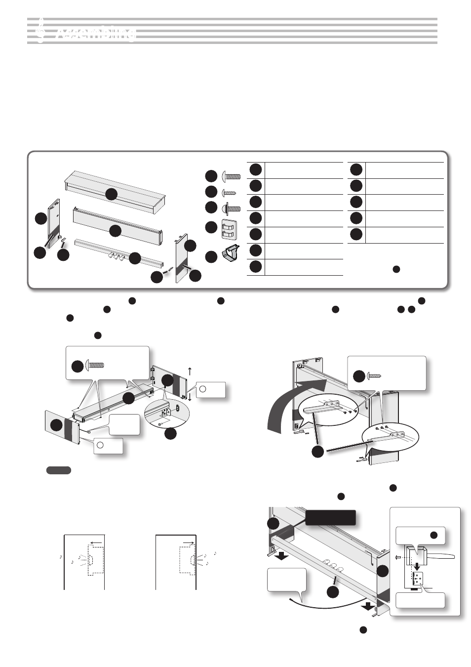
1
Piano main unit
2
Side board (left)
3
Side board (right)
4
Speaker box
5
Pedal board
6
Stabilizers (left/right)
7
Protective sheets
8
Screws (large): 8 pcs.
9
Screws (small): 6 pcs.
10
Screws (with washers): 2 pcs.
11
Cord clamps: 2 pcs.
12
Headphone hook
* To prevent the side boards from
getting scratched, do not remove the
protective sheets
7
until you are
directed to do so.
1.
Attach the side board (left)
2
and the side board (right)
3
to the speaker box
4
, and hand-tighten four of the screws
(large)
8
to fasten them provisionally (four locations) .
Attach the speaker box so that the speaker cord is on the same side as
the left side board
2
.
L Mark
Speaker
cord
2
Front
Rear
R Mark
4
3
8
Screws (large): use four screws
8
MEMO
The speaker box can also be installed so that it faces toward the
rear instead of toward the front. Having the speaker box face
out the rear of the instrument allows the speakers to be directed
toward listeners when the back of the instrument faces the
audience.
Normal direction
Speaker box
Speaker box
Front
Front
Rear
Rear
When facing to the rear
2.
Place the unit upright, and use the screws (small)
9
to
fasten the stabilizers
6
to the side boards
2
,
3
(six
locations) .
When standing the assembled unit up, grasp near the speaker box,
and gently raise the assembly.
Take care not to attach the left and right stabilizer to the wrong sides.
Left
Right
Front
Rear
6
Screws (small): use six screws
9
3.
Place the pedal board onto the metal fi xtures .
If you fi nd it diffi cult to attach the pedal board
5
, slightly loosen the
speaker box screws (large)
8
that you fastened provisionally in step 1.
5
2
3
Avoid scratches!
Putting the Pedal Board
(a lateral view)
Pedal board
5
Metal fi xtures
Extend the
pedal cord
4.
Remove the protective sheets
7
from each side board .
Check the Parts
1
2
3
7
7
4
5
6
6
8
9
10
11
12
When moving the unit
If you need to move the unit, close the keyboard cover and
disconnect the AC adaptor. With at least one other person
helping you, lift the unit horizontally and carry it, taking care
not to pinch your hands or drop the unit on your feet.
5.
Hand-tighten the screws (large)
8
to provisionally fasten
the pedal board
5
to the side boards
2
,
3
(two locations) .
3
2
5
Screws (large): use two screws
8
6.
Firmly tighten each of the side board screws (four locations)
that you provisionally tightened in step 1, making sure that
they are secure .
2
3
7.
Step on the pedals of the pedal board
5
, and make sure
that the rubber feet on the bottom of the pedals are in
contact with the fl oor . Firmly tighten the pedal board
screws
8
(two locations) that you provisionally tightened
in step 5, making sure that they are secure .
5
8.
Align the protruding screws (one each at right and left)
on the bottom of the piano
1
with the openings in the
metal fi ttings on the side board
2
,
3
, then slide the piano
forward until the screws are held in place .
Place the keyboard so that it is centered, both front to back and left
to right.
NOTE
Grasp the piano
1
in the middle at the front and rear, taking care
not to pinch your hands.
1
Screws (large): use two screws
8
Used in step 9.
Front
Please don’t
get your fi ngers
pinched
9.
Use the screws (large)
8
to fasten the piano main unit
1
to
the side boards
2
,
3
(one each for the right and left) .
Make sure to insert the screws
8
by hand and give them a few turns
by hand before using a screwdriver to tighten them.
10.
Connect the speaker cord extending from the rear of the
speaker box to the piano main unit’s speaker connector .
Rear DP90/DP90S
Hold and insert the cord so that the
clip portion extends into the stand
and is securely connected.
Speaker connector
Clip
portion
Speaker cord
11.
Use screws (with washers)
10
to fasten the headphone hook
12
.
Screws (with washers): use two screws
10
12.
Connect the AC adaptor to the DC In jack, the pedal cord to
the Pedal jack .
Firmly plug the AC adaptor
and the pedal cord all the way
into the sockets.
Pedal cord
AC adaptor
13.
Connect the supplied AC adaptor and power cord .
Place the AC adaptor so the side with the indicator faces upwards and
the side with textual information faces downwards. The indicator will
light when you plug the AC adaptor into an AC outlet.
To AC outlet
Power cord
14.
As necessary, affi x cord clamps to fasten the pedal cord .
Cord clamps
Example attachment location
54