P. 47, Changing the usb driver settings (usb driver), Controlling video equipment (visual control mode) – Roland DP90 User Manual
Page 47: Specifying the visual control channel, Various settings (function mode), What is midi visual control, What is v-link, Connection examples, Visual control function chart
Various Settings (Function Mode)
Indication
Value
Explanation
USB Drv
Changing the USB Driver Settings (USB Driver)
Normally, you don’t need to install a driver in order to connect the unit to your computer. However, if some problem occurs, or if
the performance is poor, using the Roland original driver may solve the problem.
In this case, set the unit’s “USB Driver” setting to “ORG,” and then install the driver in your computer.
After changing this setting, you need to turn off the unit, then turn it back on again.
MEMO
This setting is automatically saved in the unit.
For details on downloading and installing the Roland original driver, refer to the Roland website.
Roland website:
http://www.roland.com/
GEN
Choose this if you want to use the generic USB driver that was included with your computer. Normally, you should use this mode.
ORG
Choose this if you want to use a USB driver downloaded from the Roland website.
USB Mode
Changing the USB flash drive Setting (USB Memory Mode)
In some cases, when USB flash drive is connected to the USB memory port, it may take longer for data to be loaded, or data may fail to be loaded
successfully. If this occurs, you may be able to solve the problem by changing the USB flash drive setting.
When the unit left the factory, this was set to “2” Normally, there is no need to make this setting.
After changing this setting, you need to turn off the unit, then turn it back on again.
MEMO
This setting is automatically saved in the unit.
1, 2
VC Mode
Controlling Video Equipment (Visual Control Mode)
Visual Control is a function that lets you control images along with your performance. If you’ve set Visual Control mode to MVC or VLNK, playing the
keyboard of unit will control the images produced by the Visual Control device connected to unit using a MIDI cable.
OFF
Visual Control is off.
MVC
MIDI Visual Control mode is selected.
VLNK
V-LINK mode is selected.
VC Ch (*1)
Specifying the Visual Control Channel
Here’s how to specify the channel on which messages used to control video will be sent.
1–16
Specifies the MIDI channel used to transmit MIDI messages to the Visual Control device.
What is MIDI Visual Control?
MIDI Visual Control is an internationally-used
recommended practice that was added to the
MIDI specification so that visual expression
could be linked with musical performance. Video equipment
that is compatible with MIDI Visual Control can be connected to
electronic musical instruments via MIDI in order to control video
equipment in tandem with a performance.
What is V-LINK?
V-LINK is Roland’s proprietary specification that allows visual
expression to be linked with musical performance. Video
equipment that is compatible with V-LINK can be connected to
electronic musical instruments via their MIDI ports, making it
easy to enjoy a variety of visual effects that are linked with the
performance.
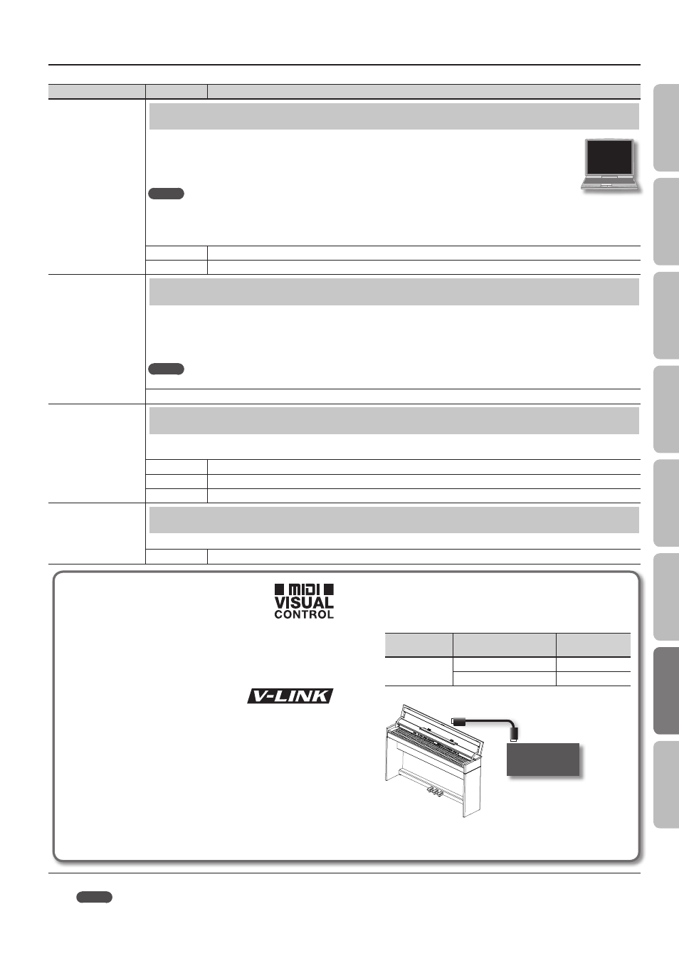
Connection examples
Connect a MIDI cable from this unit’s MIDI Out connector (p. 11) to
the MIDI In connector of your Visual Control compatible device.
* You’ll need a MIDI cable (sold separately) in order to connect
this unit to a device that supports Visual Control.
Visual control function chart
Playing the lowest 12 keys of this unit (A0–G#1) will transmit the
following MIDI messages.
Visual Control
function
Transmitted MIDI message
Unit’s operation
Switch images
CC 0 (Bank Select): 0–4
Play black keys
Program Change: 1–7
Play white keys
Visual Control
compatible video
equipment
MIDI In connector
MIDI Out connector
MEMO
(*1) This parameter can be saved by the “Memory Backup” operation (p. 39).
47
O
per
ation G
uide
Panel Descriptions
Bef
or
e
You P
la
y
Per
forming
Pr
ac
ticing
Con
venien
t F
unc
tions
A
ppendix
Func
tion M
ode