Gas supply – Raypak 500 User Manual
Page 16
Gas Supply
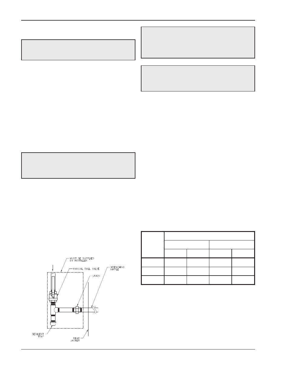
Gas piping must have a sediment trap ahead of the
heater gas controls, and a manual shut-off valve lo-
cated outside the heater jacket. It is recommended
that a union be installed in the gas supply piping adja-
cent to the heater for servicing. The gas supply
pressure to the heater must not exceed 10.5 in. WC for
natural gas or 13.0 in. WC for propane gas. A pounds-
to-inches regulator must be installed to reduce the gas
supply pressure if it is higher than noted above. This
regulator should be placed a minimum distance of 10
times the pipe diameter upstream of the heater gas
controls. Refer to Table J for maximum pipe lengths.
Gas Supply Connection
The heater must be isolated from the gas supply pip-
ing system by closing the upstream manual shut-off
valve during any pressure testing of the gas supply
piping system at test pressures equal to or less than
1/2 psi (3.45 kPa). Relieve test pressure in the gas
supply line prior to re-connecting the heater and its
manual shut-off valve to the gas supply line. FAILURE
TO FOLLOW THIS PROCEDURE MAY DAMAGE
THE GAS VALVE. Over-pressurized gas valves are
not covered by warranty. The heater and its gas con-
nections shall be leak-tested before placing the
appliance in operation. Use soapy water for leak test.
DO NOT use an open flame.
DANGER: Make sure the gas on which the heater
will operate is the same type as specified on the rat-
ing plate.
CAUTION: The heater must be disconnected from
the gas supply during any pressure testing of the gas
supply system at test pressures in excess of 1/2 psi
(3.45 kPa).
Gas Supply Pressure
A minimum of 4.0 in. WC and a maximum of 10.5 in.
WC upstream gas pressure is required under load and
no-load conditions for natural gas. A minimum of 4.0
in. WC and a maximum of 13.0 in. WC is required for
propane gas. The gas pressure regulator(s) supplied
on the heater is for low-pressure service. If upstream
pressure exceeds these values, an intermediate gas
pressure regulator, of the lockup type, must be
installed.
When connecting additional gas utilization equipment
to the gas piping system, the existing piping must be
checked to determine if it has adequate capacity for
the combined load. The gas valve pressure regulator
on the heater is nominally preset as noted in Table I.
During normal operation, carbon dioxide should be 8.5
to 9.0% at full fire for natural gas and between 9.0 and
9.5% for propane gas. Carbon monoxide should be
‹150 ppm.
Fig. 10: Gas Supply Connection
CAUTION: Do not use Teflon tape on gas line pipe
thread. A pipe compound rated for use with natural
and propane gases is recommended. Apply
sparingly only on male pipe ends, leaving the two
end threads bare.
CAUTION: Support gas supply piping with
hangers, not by the heater or its accessories. Make
sure the gas piping is protected from physical
damage and freezing, where required.
NOTE: Manifold pressures should be ±0.3 in. WC.
Table I: Manifold Gas Pressure Settings
16
Model
No.
Manifold Pressure (in. WC)
Natural Gas
Propane Gas
High
Low
High
Low
300
-0.2
-0.1
-0.2
-0.1
500
-0.3
-0.1
-0.3
-0.1
850
-3.2
-0.2
-2.7
-0.1