Waveform generation timing connections, Wftrig signal, Figure 4-24. wftrig input signal timing – National Instruments NI 6014 User Manual
Page 57: Waveform generation timing connections -31, Wftrig signal -31
Chapter 4
Connecting Signals
© National Instruments Corporation
4-31
Waveform Generation Timing Connections
The analog group defined for the device is controlled by WFTRIG,
UPDATE*, and UISOURCE.
WFTRIG Signal
Any PFI pin can externally input the WFTRIG signal, which is available as
an output on the PFI6/WFTRIG pin.
As an input, WFTRIG is configured in the edge-detection mode. You can
select any PFI pin as the source for WFTRIG and configure the polarity
selection for either rising or falling edge. The selected edge of WFTRIG
starts the waveform generation for the DACs. The update interval (UI)
counter is started if you select internally generated UPDATE*.
As an output, WFTRIG reflects the trigger that initiates waveform
generation, even if the waveform generation is being externally triggered
by another PFI. The output is an active high pulse with a pulse width of
50 to 100 ns. This output is set to high-impedance at startup.
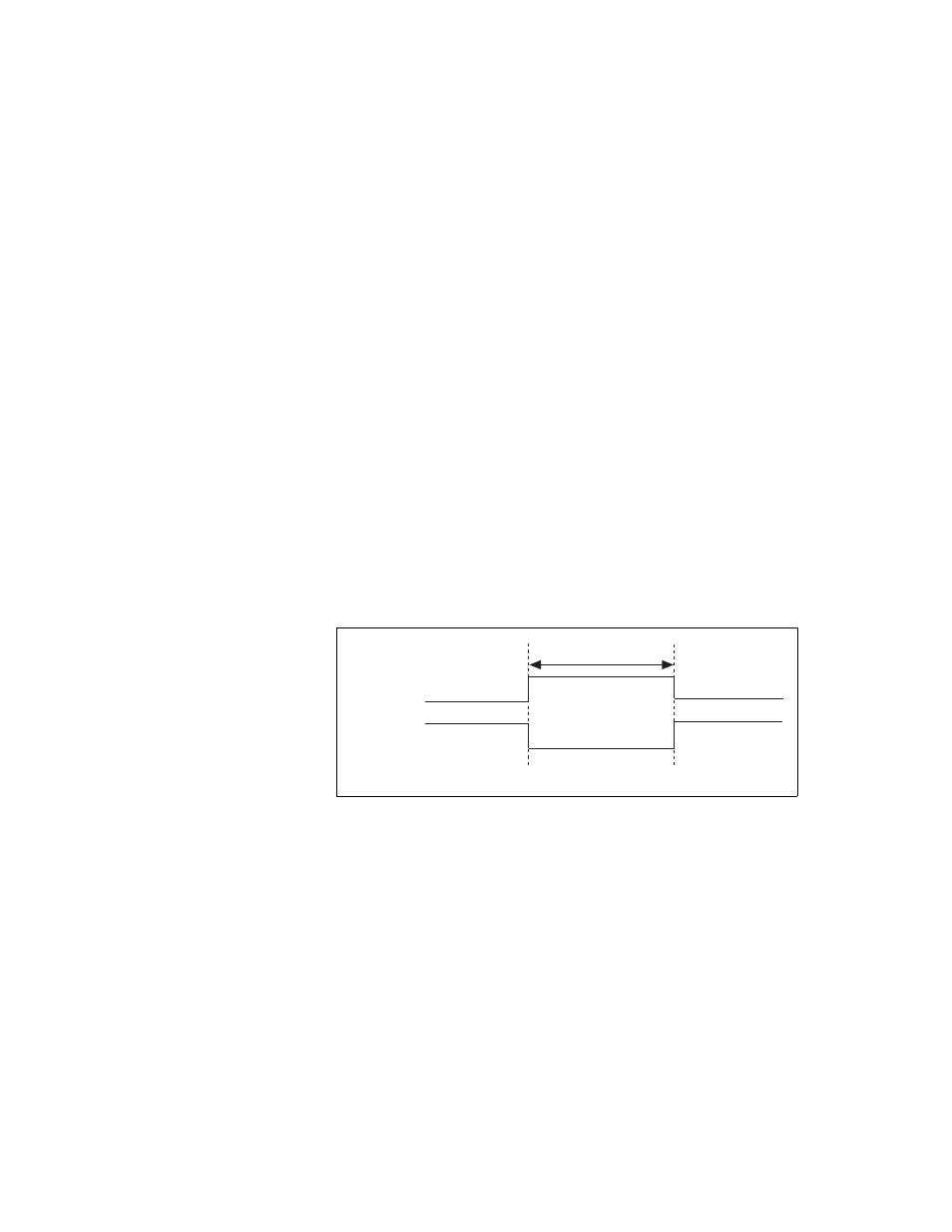
Figures 4-24 and 4-25 show the input and output timing requirements for
WFTRIG.
Figure 4-24. WFTRIG Input Signal Timing
Rising-Edge
Polarity
Falling-Edge
Polarity
t
w
= 10 ns minimum
t
w