Connecting digital i/o signals, Figure 4-9. digital i/o connections, Connecting digital i/o signals -18 – National Instruments NI 6014 User Manual
Page 44
Chapter 4
Connecting Signals
4-18
ni.com
Connecting Digital I/O Signals
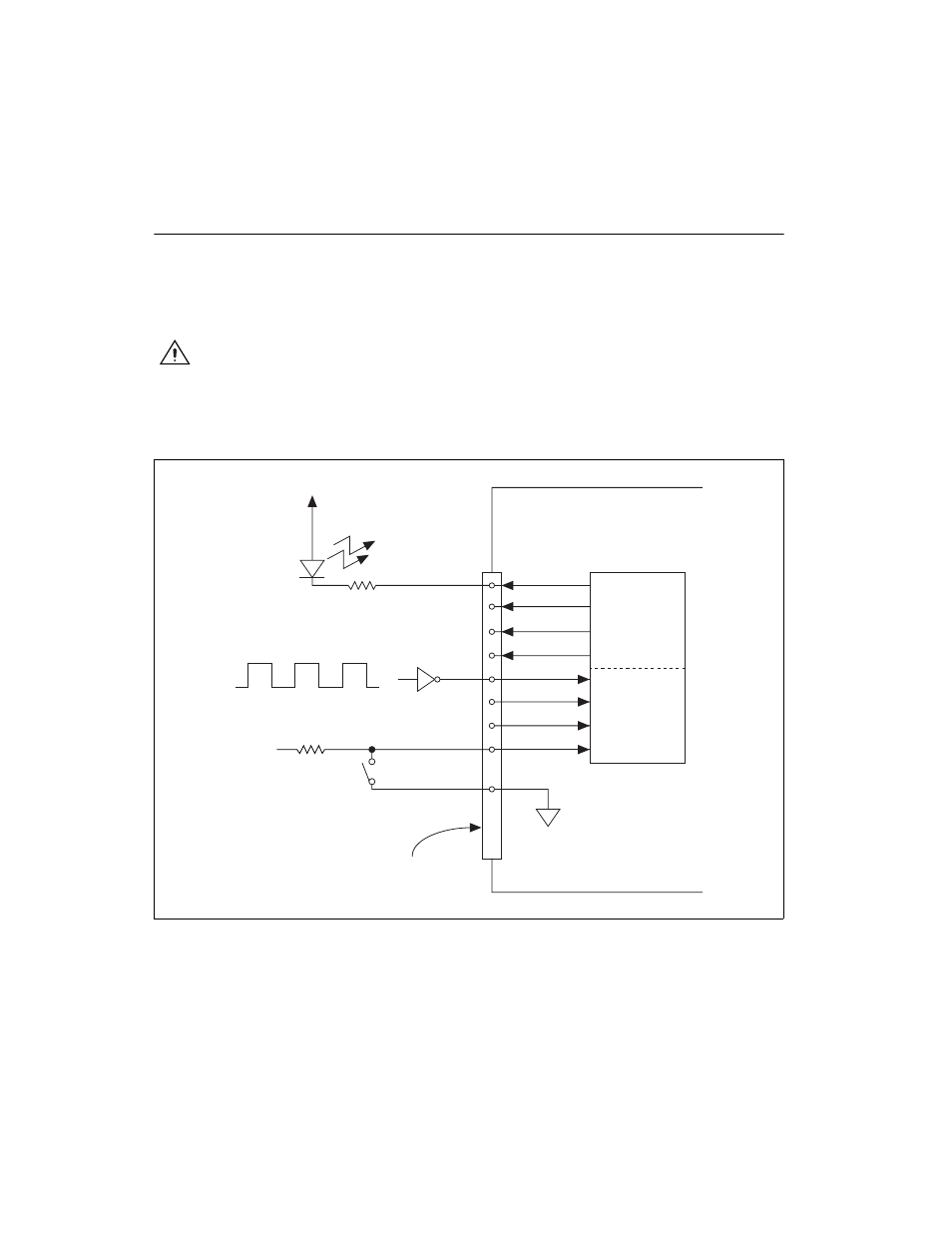
The DIO signals on the NI 6013/6014 are DIO<0..7> and DGND.
DIO<0..7> are the signals making up the DIO port, and DGND is the
ground-reference signal for the DIO port. You can program all lines
individually to be inputs or outputs.
Caution
Exceeding the maximum input voltage ratings, which are listed in Table 4-3, can
damage the NI 6013/6014 and the computer. NI is not liable for any damage resulting from
such signal connections.
Figure 4-9 shows signal connections for three typical DIO applications.
Figure 4-9. Digital I/O Connections
+5 V
LED
TTL Signal
+5 V
Switch
I/O Connector
DGND
DIO<0..3>
DIO<4..7>
This manual is related to the following products: