Connect the router, R5100 serial, R5200 dds and r5300 t1 – Netopia R5300 User Manual
Page 23: Connect the router -3, R5100 serial -3, R5200 dds and r5300 t1 -3
Making the Physical Connections 3-3
C
C
C
Co
o
o
on
n
n
nn
n
n
nee
e
ecccctttt tttth
h
h
hee
e
e rrrro
o
o
ou
u
u
uttttee
e
errrr
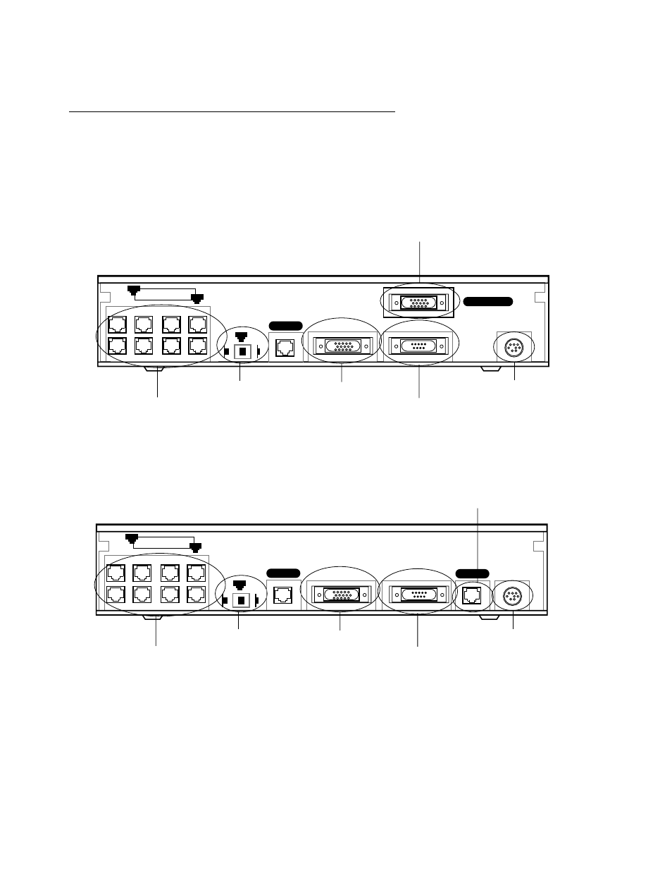
Identify the connectors and switches on the back panel and attach the necessar y Netopia Router cables.
R
R
R
R5
5
5
511110
0
0
00
0
0
0 S
S
S
See
e
errrriiiiaa
a
allll
The figure below displays the back of the Netopia R5100 Serial Router.
Netopia R5100 back panel
R
R
R
R5
5
5
52
2
2
20
0
0
00
0
0
0 D
D
D
DD
D
D
DS
S
S
S aa
a
an
n
n
nd
d
d
d R
R
R
R5
5
5
53
3
3
30
0
0
00
0
0
0 TT
T
T1111
The figure below displays the back of the Netopia R5200 DDS or R5300 T1 Router.
Netopia R5200/5300 back panel
Note: For simplicity, the remainder of this manual uses the figure above to illustrate connections.
Ethernet
Normal
Auxiliary
Console
Power
Line 1 - Serial
8 por t Ethernet hub
Crossover switch
Serial Line por t
Auxiliar y por t
Console por t
Power por t
8
1
1
Uplink
Line 2
Ethernet
Normal
Auxiliary
Console
Power
Line 1
8 por t Ethernet hub
Crossover switch
Line por t
Auxiliar y por t
Console por t
Power por t
8
1
1
Uplink
Line 2