M1112 administrator manual – Nokia M1112 User Manual
Page 27
M1112 Administrator Manual
E
Copyright Nokia Networks Oy
C33907001SE_00
3-2
3.1.1
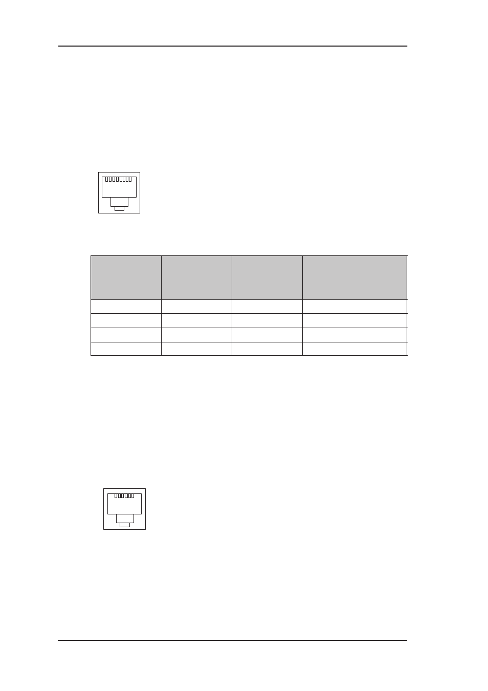
Ethernet interface
The Ethernet interface (ETH) is located on the back panel. The
Ethernet interface is a standard 10 Mbit/s half-duplex 10Base-T
interface. The mechanical connector is an 8-pin RJ-45. The pin-out
numbering is shown in Table 3-1.
1
8
Figure 3-2
ETH connector
PIN
Signal
Direction
M1112-
Ethernet
MDI signal
1
Rx+
<–
Receive data +
2
Rx–
<–
Receive data –
3
Tx+
–>
Transmit data +
6
Tx–
–>
Transmit data –
Table 3-1
Ethernet interface pin-out numbering
3.1.2
ADSL interface
The ADSL interface (DSL) is compatible with ETSI TS 101 388
specification. The mechanical connector is a 6-pin RJ-11. The pin-out
numbering is shown in Table 3-2.
1
6
Figure 3-3
DSL connector