Analog input timing signal, Ai sample clock, Figure 11. sample clock timing options – National Instruments NI WLS/ENET-9163 User Manual
Page 21: Convert behavior for analog input modules, Scanned, Analog input timing signal ai sample clock, Convert behavior for analog input modules scanned
© National Instruments Corporation
21
NI WLS/ENET-9163 Carrier User Guide and Specifications
Note
Pause triggers are only sensitive to the level of the source, not the edge.
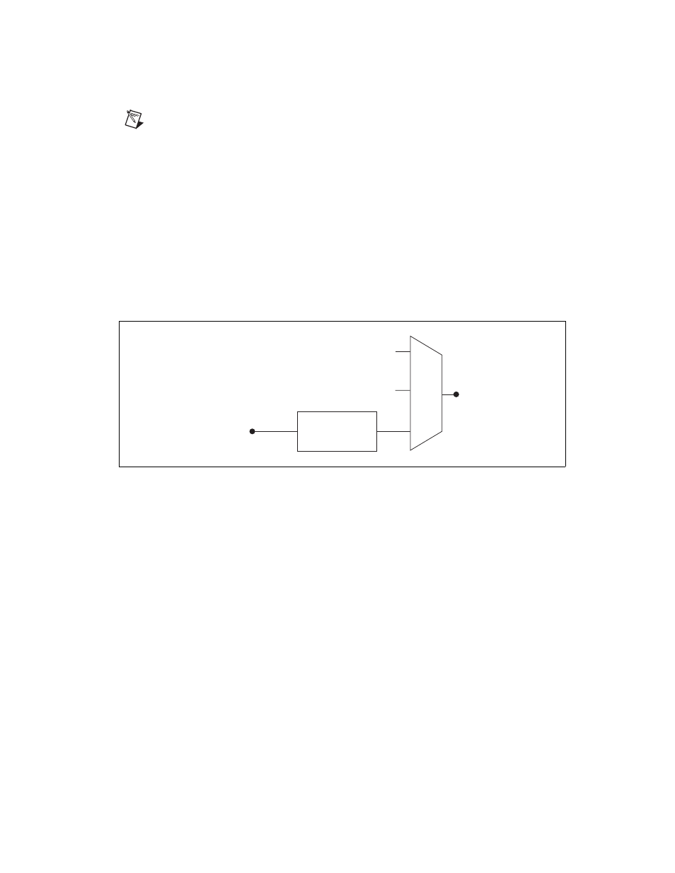
Analog Input Timing Signal
AI Sample Clock
A sample consists of one reading from each channel in the AI task.
ai/SampleClock signals the start of a sample of all analog input channels
in the task. ai/SampleClock can be generated from external or internal
sources.
Using A Digital Source
To use ai/SampleClock, specify a source and an edge on PFI 1. For more
information, refer to the Device Routing in MAX topic in the NI-DAQmx
Help.
Figure 11. Sample Clock Timing Options
Routing AI Sample Clock to an Output Terminal
You can route ai/SampleClock to the PFI 1 terminal.
Convert Behavior For Analog Input Modules
Scanned
Scanned C Series analog input modules contain a single A/D converter and
a multiplexer to select between multiple input channels. When the C Series
Module Interface receives a Sample Clock pulse, it begins generating a
Convert Clock for each scanned module in the current task. Each Convert
Clock signals the acquisition of a single channel from that module. The
Convert Clock rate depends on the module being used, the number of
channels, and the Sample Clock rate.
Programmable
Clock
Divider
ai/SampleClock Timebase
20 MHz Timebase
PFI
ai/SampleClock
Sigma-Delta Module Internal Output