Video/personal computer cables & adaptors – Panasonic PT-L759VU User Manual
Page 45
45
Video/Personal Computer Cables & Adaptors
Pin No.
Signal name
1
T.M.D.S Data 2-
2
T.M.D.S Data 2+
3
T.M.D.S Data 2 Shield
4
NC
5
NC
6
DDC Clock
7
DDC Data
8
NC
9
T.M.D.S Data 1-
10
T.M.D.S Data 1+
11
T.M.D.S Data 1 Shield
12
NC
13
NC
14
+5 V
15
GND
8
1
16
17 9
24
[ DVI-D connector ]
(On Projector)
Pin No.
Signal name
16
Hot Plug Detect
17
T.M.D.S Data 0-
18
T.M.D.S Data 0+
19
T.M.D.S Data 0 Shield
20
NC
21
NC
22
T.M.D.S Clock Shield
23
T.M.D.S Clock +
24
T.M.D.S Clock -
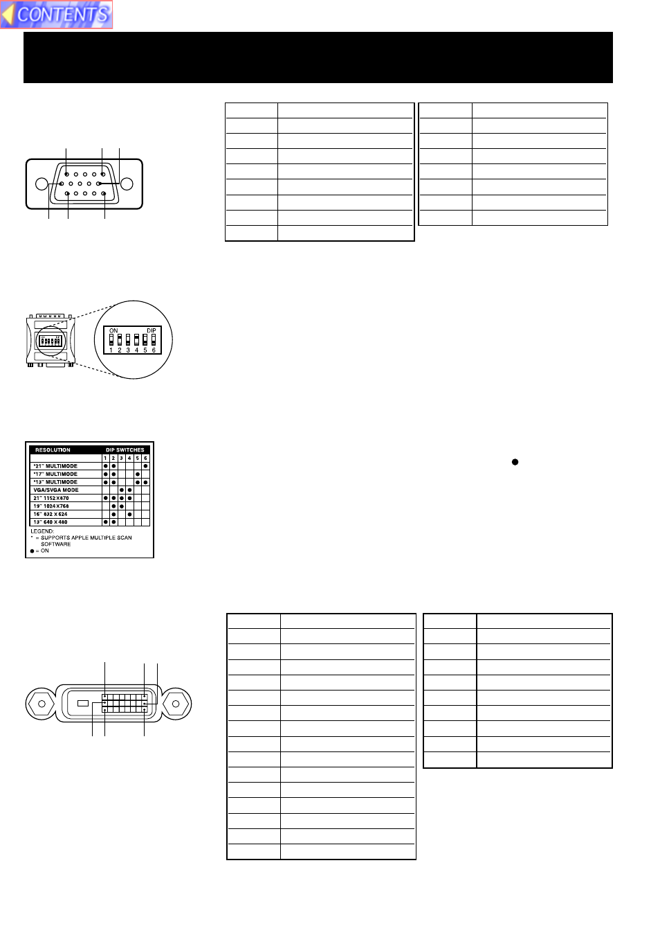
Example: If your display type is 16
″
, set DIP switches 2 and 4 on the VGA
MAC Adaptor to ON. By doing so, the signal will travel through
switches 2 and 4, and Pin No. 4 to 10 as shown in the signal chart
above.
[ VGA MAC Adaptor ]
[ Setting the DIP Switches ]
[ RGB connector ]
1
5
6
15
11
10
Pin No.
Signal name
1
R
2
G
3
B
4
NC
5
NC
6
Ground for R
7
Ground for G
8
Ground for B
Pin No.
Signal name
9
NC
10
Ground
11
NC
12
SDA
13
HD/CSYNC
14
VD
15
SCL
Find the resolution of your display type on the table shown left (also on the
adaptor). Then, set each DIP switch that is indicated by a “ ” mark to ON.
(On Projector)
[PT-L759XU only]