Reassembly instructions, Attention when cf-30 series is repaired, Setting the antenna pcb l and r – Panasonic CF-30KTPAXxM User Manual
Page 34
9-11
9.2.
Reassembly Instructions
9.2.1.
Attention when CF-30 series is repaired
• Please execute writing BIOS ID when you exchange the Main Board.
• Parts (Sheet and rubber) etc. related various the Conductive Cloth and Heat Spreader cannot be recycled. Use new parts.
9.2.2.
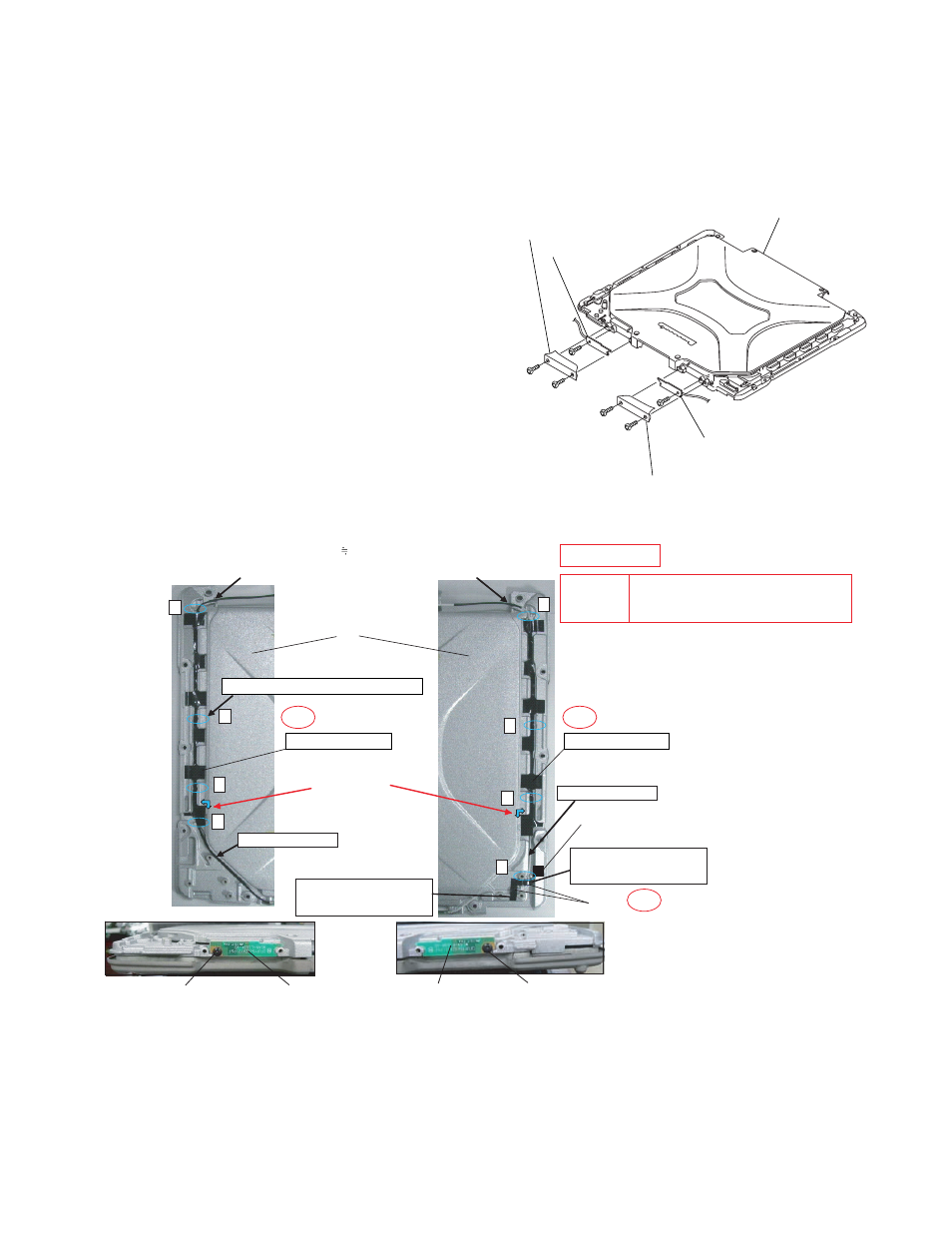
Setting the Antenna PCB L and R
1. Set the Antenna PCB L and R using the 2 Screws
2. Fix the W-LAN ANT Cover L and R using the 4 Screws
Note:
Tighten the Screws in the numbered order (No1 to No4).
Screws
Arranging the Antenna L and R Cables
LCD Rear Cabinet Ass’y
Antenna PCB R
Antenna PCB L
W-LAN ANT Cover R
W-LAN ANT Cover L
X
X
X
X
X
X
X
X
Insert the cable between the pins.
Insert the cable between the pins.
LCD Rear ASS’Y
Put it along the inside of boss on X part
Rear Cable Sheet R
Rear Cable Sheet L
Do not pinch the cable
out of the cabinet
Attach it fitting
to the corner
Coming off the tape
is arrowed
Cable color : Gray
Rear Screw Sheet
Tape
Do not pinch the cable
out of the cabinet
Match it to the concave
side and attach it between
the bosses.
Match it to the protrusion
side and attach it between
the bosses.
Place the anntena sub Tighten the screw
Tighten the screw
Place the anntena main
Safety Working
Cable color : Black
S2
Do not pinch the cable
out of the cabinet
S2
S2
Torque of tightening screw :
0.45
–
0.05
N•m(
4.5
–
0.5
kgf•cm)
CAUTION
S1:Insulation S2:Bitten S3:Sharp Edge
S4:Part No. Check S5:Other