Scenario 5 – Paradyne 3161-B3 User Manual
Page 252
F. IP Network Addressing Scenarios
F-6
February 2001
3160-A2-GB21-90
Scenario 5
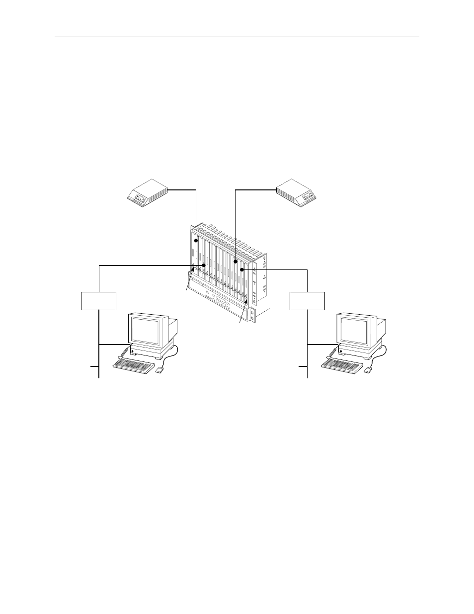
Figure F-5, Multiple COM Ports Connected to Different NMSs
, illustrates multiple
COM ports on the same carrier connected to different NMSs. This might be used
in service-provider applications, where some of the carrier's circuit cards (and their
remotes) are managed by one NMS and other cards are managed by a different
NMS. In this example, each card and remote is on a separate subnet. Also, note
that each LAN Adapter connection is on a different subnet. The subnet mask is
FF.FF.FF.00. The NMS hosts would only need routes added for the subnets that
they are to manage.
Figure F-5.
Multiple COM Ports Connected to Different NMSs
ETHERNET
135.18.23.2
496-14649-02
LAN
ADAPTER
T1
CO
MS
PH
ER
E 3
610
135.18.34.2
135.18.22.1 . . . . 135.18.37.1
135.140.22.79
COM IP
ADDRESS:
135.140.22.95
SUBNET 135.18.34.0
SUBNET 135.18.23.0
T1
CO
M
SP
HE
RE
30
00
ETHERNET
LAN
ADAPTER
135.18.40.1
COM
SPHERE 3610
SUBNET 135.140.22.0
SUBNET 135.18.40.0
COM IP
ADDRESS:
135.18.40.5