Appendix c: connecting audio devices, Setting up standard audio inputs, Setting up optional audio connections – Pelco DX8100 User Manual
Page 68: 91 audio connector installation, Figure 90. audio connector installation
68
C2629M-A (6/07)
Appendix C: Connecting Audio Devices
This appendix describes how to connect audio devices to the DX8100. Before using the audio recording features of the DX8100, consult the
applicable laws regarding audio surveillance recording for your location.
SETTING UP STANDARD AUDIO INPUTS
The DX8100 provides two standard audio line in and microphone inputs that support 2-channel (right/left) audio recording. Use a miniature phone
plug to connect audio devices to the DX8100. For information about configuring the DX8100 to record audio, refer to the DX8100 Operation and
Programming Server Application Software manual or online Help system.
SETTING UP OPTIONAL AUDIO CONNECTIONS
If more audio inputs are required, the DX8100 supports an 8-channel (DX8108-AUD) and 16-channel (DX8116-AUD) audio expansion option.
Expansion audio inputs correspond to video inputs as follows:
•
An 8-channel accepts up to 8 audio inputs.
•
A 16-channel DVR accepts up to 16 audio inputs.
•
A 24-channel DVR accepts up to 24 audio inputs.
•
A 32-channel DVR accepts up to 32 audio inputs.
Audio and video inputs are configured in a one-to-one relationship. For example, audio input seven corresponds to video channel seven.
The DX8100 accepts up to 32 individual monaural audio inputs. Each input is designed to receive a line-level, analog audio signal that is sampled
at a rate of 48 kHz (16 bits) by the DX8108-AUD’s digital analog converters (DAC). To minimize the amount of storage required to store audio
data, the audio stream is down-sampled to 8 kHz (8 bits) for storage and playback.
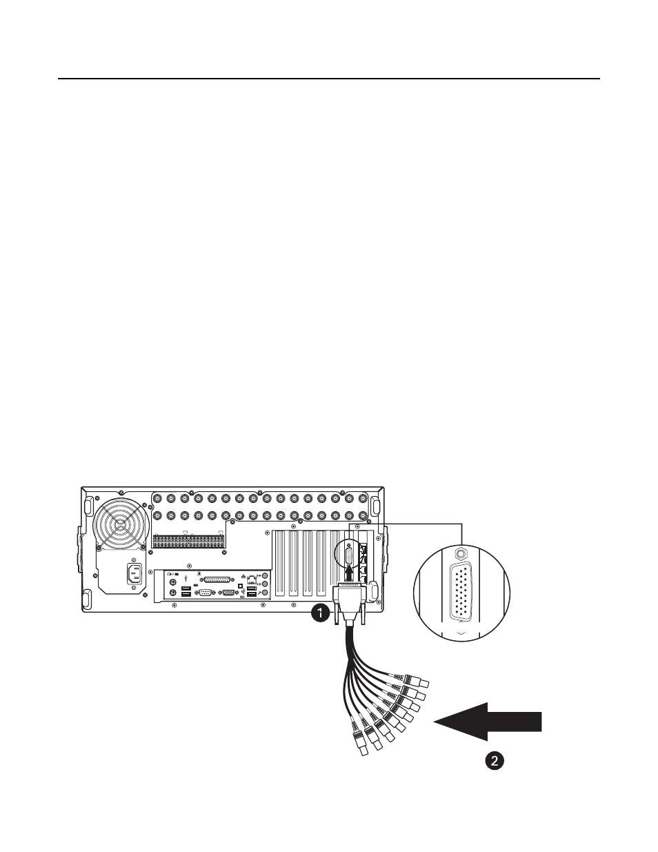
Audio input is provided through an audio cable consisting of eight RCA connectors wired to a 26-pin breakout connector.
The 26-pin connector connector plugs into the 26-pin Sub-D socket on the capture card. Depending on your system’s configuration, either one or
two breakout cables will be required to connect the DVR to an audio system.
1. Connect the 26-pin audio breakout connector to the 26-pin Sub-D socket on the capture card to provide 8 or 16 individual audio inputs. Refer
to Figure 91.
IN1
IN2
IN3
IN4
IN5
IN6
IN7
IN8
IN9
IN10
IN11
IN12
IN13
IN14
IN15
IN16
OUT16
OUT15
OUT14
OUT13
OUT12
OUT11
OUT10
OUT9
OUT8
OUT7
OUT6
OUT5
OUT4
OUT3
OUT2
OUT1
ALARM INPUTS
RELAY OUTPUTS
1 2 2 4 5 6 7 8 GND
9 10 11 12 13 14 15 16
1 2 2 4 5 6 7 8 GND
9 10 11 12 13 14 15 16
AUDIO
(PREAMP)
OPTIONAL AUDIO INPUTS 1-8
FOR 8 AND 16 CHANNEL DVRS.
Figure 90. Audio Connector Installation