Hardware setup, Basic connections, 9 basic connections – Pelco DX8100 User Manual
Page 21: Video coaxial cable requirements, Connect the mouse to the top ps/2 input, Connect the keyboard to the bottom ps/2 input, Connect a vga monitor (not supplied)
C2629M-A (6/07)
21
Hardware Setup
BASIC CONNECTIONS
IN1
IN2
IN3
IN4
IN5
IN6
IN7
IN8
IN9
IN10
IN11
IN12
IN13
IN14
IN15
IN16
OUT16
OUT15
OUT14
OUT13
OUT12
OUT11
OUT10
OUT9
OUT8
OUT7
OUT6
OUT5
OUT4
OUT3
OUT2
OUT1
ALARM INPUTS
RELAY OUTPUTS
1 2 2 4 5 6 7 8 GND
9 10 11 12 13 14 15 16
1 2 2 4 5 6 7 8 GND
9 10 11 12 13 14 15 16
VGA
KEYBOARD
MOUSE
POWER
CONNECTION
SPECTRA
CAMERA
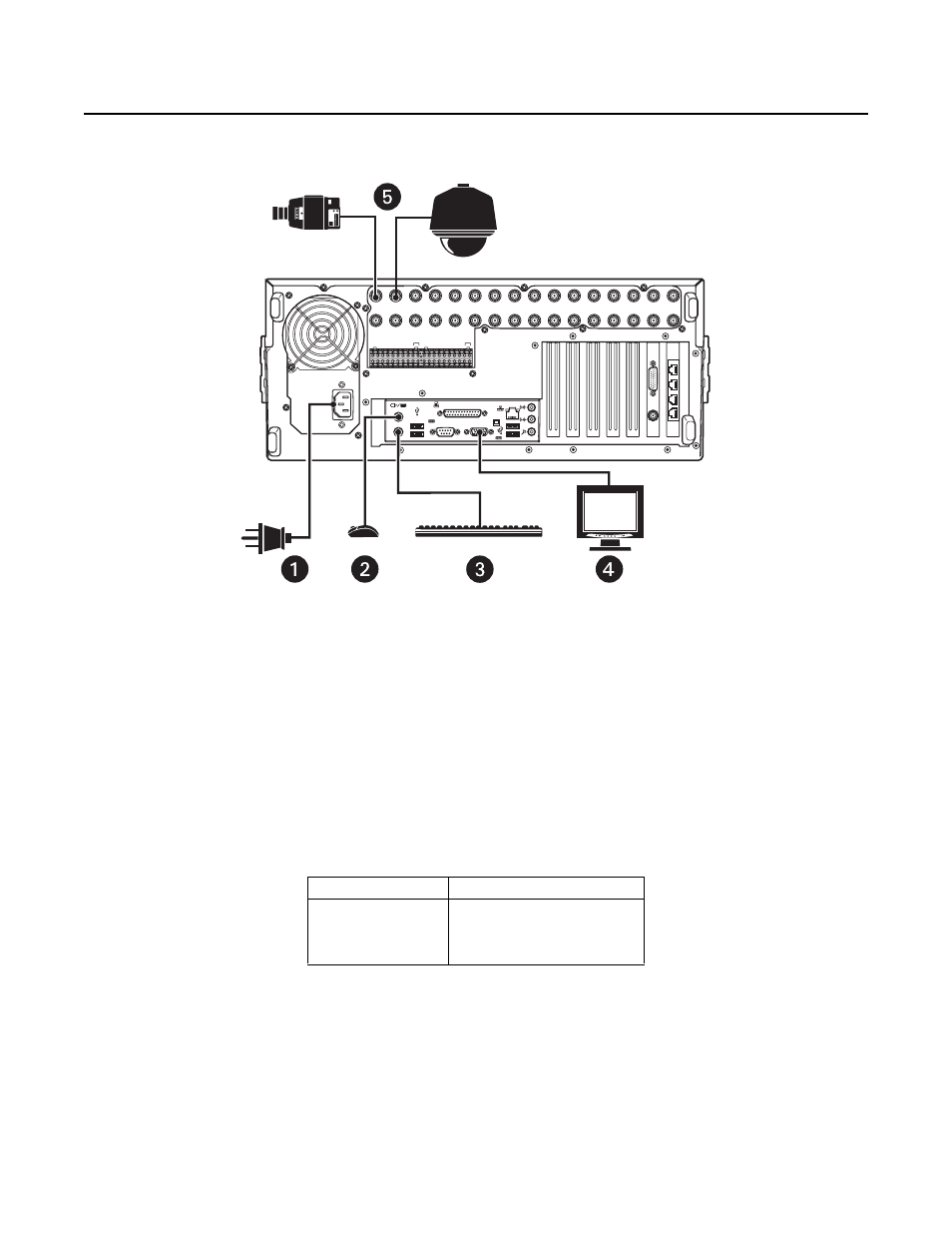
Figure 9. Basic Connections
Make the following connections on the rear of the recorder. Refer to Figure 9.
ì
Connect the appropriate power cord to the back of the unit and to a power source.
The DX8100 contains an autoranging power supply. It is recommended that the recorder be connected to an uninterruptible power supply
(UPS) capable of supplying 2 A for 120 VAC power systems or 1 A for 230 VAC power systems.
î
Connect the mouse to the top PS/2 input.
ï
Connect the keyboard to the bottom PS/2 input.
ñ
Connect a VGA monitor (not supplied).
ó
Connect the cameras to the BNC connectors. Refer to Table B for video coaxial cable requirements. Connect power to the cameras.
Table B. Video Coaxial Cable Requirements
Cable Type*
Maximum Distance
RG59/U
750 ft (229 m)
RG6/U
1,000 ft (305 m)
RG11/U
1,500 ft (457 m)
*Minimum cable requirements:
75 ohms impedance
All-copper center conductor
All-copper braided shield with 95% braid coverage
When connecting cameras using these types of cable, use a
patch panel. Do not connect these cables directly to the
DX8100.