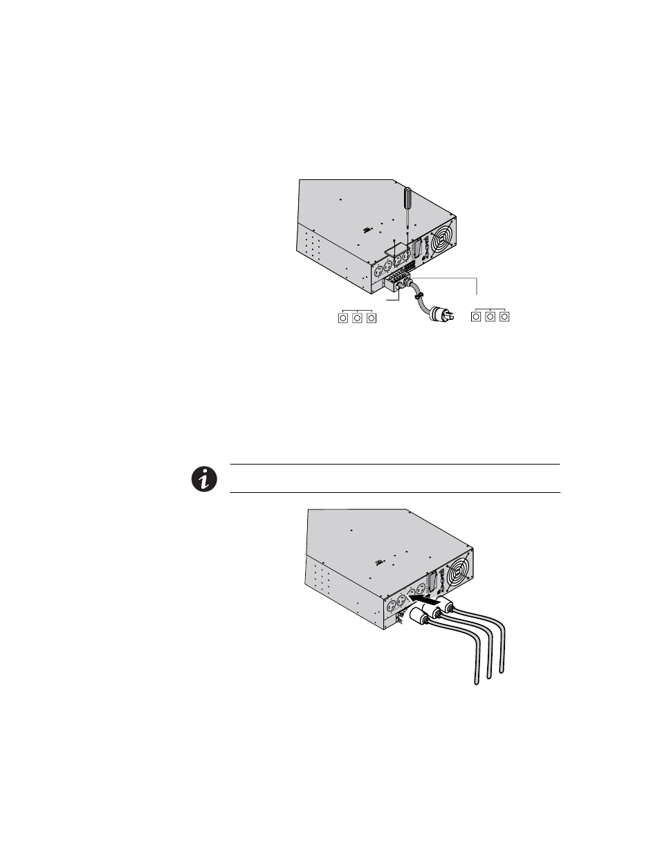
Figure 26. connecting the power cords (u models), Output terminal input terminal, Installation – Powerware 9135 Two-in-One UPS 5000/6000 VA User Manual
Page 49: Gnd l2 (n) l1 gnd l2 (n) l1, Eaton powerware
INSTALLATION
EATON Powerware
®
9135 Two−in−One UPS (5000/6000 VA) User’s Guide
S 164201726 Rev 1
www.powerware.com
43
BAT
T
. NO
.
200
−25
0V~,
24A
RPO
RS−232
CAUT
IO
N:
DO
N
O
T D
IS
CO
NNECT
BATT
ERY C
ABLE
UNDER L
O
AD
BATT
ERY
CO
NNECTO
R
180
VD
dc
Output Terminal
Input Terminal
GND L2
(N)
L1
GND L2
(N)
L1
Figure 25. Installing the Input and Output Cables (U Models)
5.
Replace the terminal block cover and tighten the cables.
6.
Secure the terminal block cover with the two screws removed in
Step 1.
7.
Plug the equipment to be protected into the appropriate UPS output
receptacles.
NOTE If more than one load is connected to the UPS, the total capacity of the loads should
not exceed 30A.
BAT
T
. NO
.
200
−25
0V~,
24A
RPO
RS−
232
CAUT
ION:
DO
N
O
T D
IS
CO
NNECT
BATTERY C
ABLE
UNDER L
O
AD
BATTE
RY
CO
NNECTO
R
180
Vdc
c
Figure 26. Connecting the Power Cords (U Models)