0 appliance operation – Baxi Potterton 80 HE User Manual
Page 7
3.0 Appliance Operation
7
NOTE: All delay timers mentioned in 3.1 and 3.3 are
overridden by domestic hot water demand.
3.1
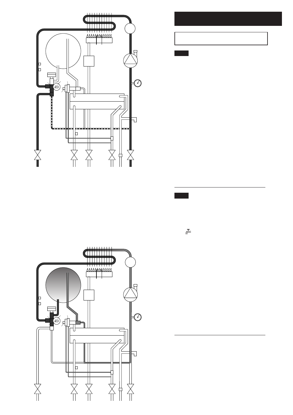
Central Heating Mode (Fig. 2)
1. With a demand for heating, the pump circulates water
through the primary circuit. At a pre-determined flow
rate the central heating flow switch operates, initiating
the ignition sequence.
2. The main burner ignites at low rate, then the gas valve
controls the gas rate to maintain the heating temperature
measured by the temperature sensor.
3. When the flow temperature exceeds the setting
temperature, a 3 minute delay occurs before the burner
relights automatically (anti-cycling). The pump continues
to run during this period.
4. When the demand is satisfied the burner is
extinguished and the pump continues to run for a period
of 30 minutes (Pump Overrun).
5. If there is no other demand the pre-heat function will
operate if switched on (see Section 3.2).
3.2
Domestic Hot Water - Preheat Mode
(Fig. 3)
1. With the pre-heat function switched on (pre-heat
control fully clockwise), priority is given to the
replenishment of the pre-heat store. The DHW mode
neon ( ) will flash during this function.
2. The diverter valve remains in the DHW priority
position. This allows the pump to circulate hot water to
the store and back to the primary heat exchanger via the
bypass pipe.
3. The automatic ignition sequence commences after
approximately 25 seconds and the burner will light.
4. When the store reaches the desired temperature the
burner is extinguished. The pump continues to run for a
period of 30 seconds.
5. Following a demand for domestic hot water or the
end of a central heating ON period, the pre-heat
function restarts.
27
19
16
15
14
13
12
10
9
11
8
17
21
23
20
22
19
28
26
5
6
7
2
3
4
1
25
24
18
1
Primary Heat Exchanger
2
Burner
3
Ignition Electrode
4
Flame Sensing Electrode
5
Gas Valve
6
Pump
7
Automatic Air Vent
8
Plate Heat Exchanger
9
Flow Sensor with Filter
10
Pressure Relief Valve
11
Boiler Drain Point
12
Heating Return
13
Cold Water Inlet On/Off Valve and Filter
14
Gas Inlet
15
Domestic Hot Water Outlet
16
Heating Flow
17
Pressure Gauge
18
Hydraulic Pressure Sensor Microswitch
19
Automatic By-Pass
20
Hydraulic Pressure Sensor
21
Diverter Valve Assembly
22
Domestic Hot Water Flow Priority Assembly
23
Domestic Hot Water Flow Priority Microswitch
24
Safety Thermostat
25
Central Heating Temperature Sensor
26
Expansion Vessel & Pre-Heat Store
27
Domestic Hot Water Temperature Sensor
28
Secondary Heat Exchanger
Key
Central Heating Mode
Fig. 2
27
19
16
15
14
13
12
10
9
11
8
17
21
23
20
22
19
26
5
6
7
2
3
4
1
25
24
18
28
Domestic Hot Water - Preheat Mode
Fig. 3