0 general layout – Baxi Potterton 80 HE User Manual
Page 6
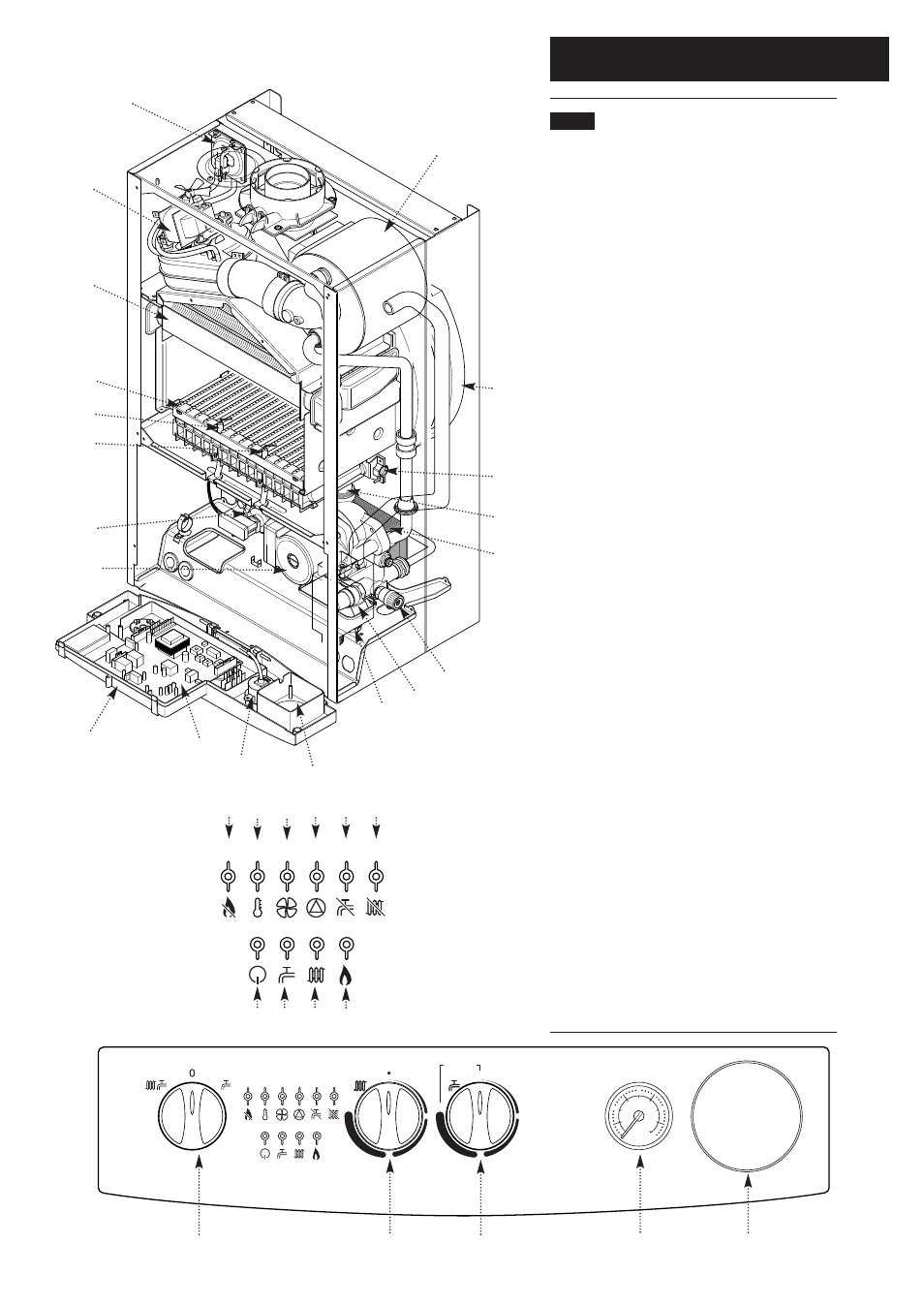
2.0 General Layout
6
2.1
Layout
1.
Air Pressure Switch
2.
Expansion Vessel & Pre-Heat Store
3.
Burner Manifold
4.
Automatic Air Vent
5.
DHW Plate Heat Exchanger
6.
Circulation Pump
7.
Drain Off Point
8.
Pressure Relief Valve
9.
Position for Optional Integral Timer
10.
Central Heating System Pressure Gauge
11.
PCB
12.
Control Box
13.
3-Way Valve Assembly
14.
Condensate Trap
15.
Flame Sensing Electrode
16.
Spark Electrode
17.
Burner
18.
Primary Heat Exchanger
19.
Fan Assembly
20.
Secondary Heat Exchanger
21.
On/Off/Reset Selector Switch
22.
Central Heating Temperature Control
23.
Domestic Hot Water Pre-Heat Control
24.
Flame Failure or Blocked Condensate Drain
25.
Safety Thermostat Activated (Boiler or Flue)
26.
Fault on Fan or Flue
27.
Fault on Pump or Low System Pressure
28.
Fault on Hot Water Sensor
29.
Fault on Central Heating Sensor
30.
Power On
31.
Domestic Hot Water Mode
32.
Central Heating Mode
33.
Burner On
When neons 24 to 29 are constantly illuminated, they
indicate the temperature of the central heating water.
19
18
17
14
15
16
13
12
11
10
9
21
22
23
10
9
7
6
3
4
5
8
2
1
30
o
40
o
50
o
60
o
70
o
80
o
2
1
0
4
3
bar
Reset
OFF
ON
PREHEAT
30
o
40
o
50
o
60
o
70
o
80
o
24
25
26
27
28
29
30
31
32
33
20