0 commissioning the boiler, 2 checking the burner pressure – Baxi Potterton 80 HE User Manual
Page 27
9.0
Commissioning the Boiler
27
OUT
MIN
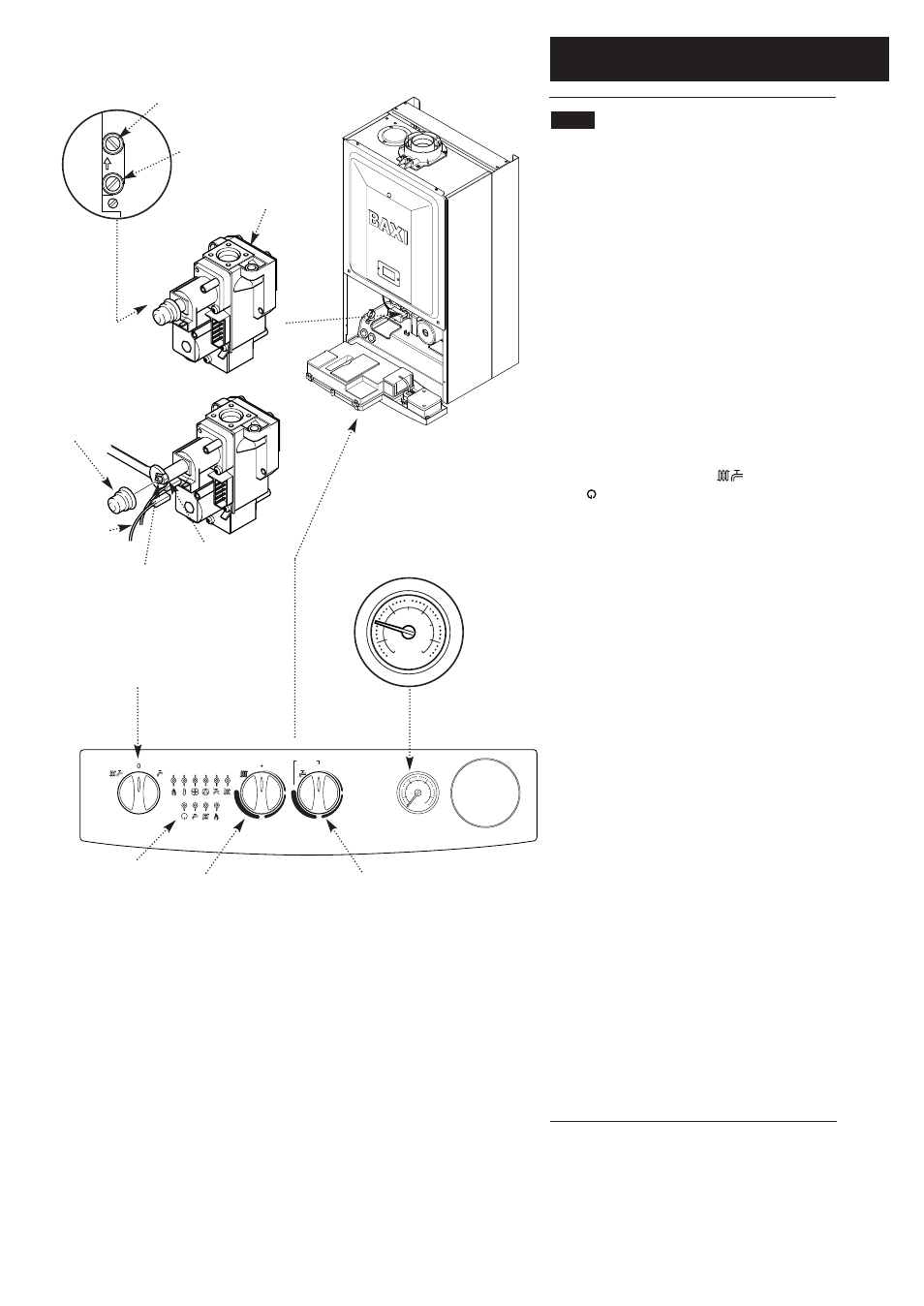
Burner Pressure Test
Point Sealing Screw
Fig. 34
9.2
Checking the Burner Pressure
1. Turn on the gas and electrical supplies to the boiler
and ensure that all external controls are calling for heat.
2. Set the hot water and central heating temperature
controls to maximum and the selector switch to the
OFF position (Fig. 37).
3. Slacken the pressure test point sealing screw (Fig. 34)
on the gas valve and connect a pressure gauge.
4. Disconnect the sensing tube from the gas valve (Fig.
34).
5. Turn the selector switch fully anticlockwise against the
spring pressure to position R and hold for 2 seconds to
reset the boiler.
6. Turn the selector switch to the Central Heating and
Domestic Hot Water position ( ). The power ON
neon ( ) will illuminate (Fig. 37).
7. Turn on a hot water tap to give a flow rate of at least
10 l/min.
8. The pressure should be :-
Instant
Instant
80 HE
105 HE
NG
10.2mbar
12.1mbar
Propane
21.8mbar
32.3mbar
If not, check that the gas supply pressure is correct
(Natural Gas 20mbar, and Propane 37mbar).
9. The pressure can be adjusted if required.
10. To check and set minimum pressure first remove
one of the modulator wires.
Adjusting the Pressure (Fig 35)
11. Remove the plastic protection cap from the pressure
adjustment nuts on the valve.
12. The smaller nut (5mm) adjusts minimum pressure
and the larger nut (8mm) maximum pressure.
13. Using a suitable spanner adjust the relevant nut until
the correct pressure is achieved.
14. Once the pressure has been set turn the boiler off
and disconnect the pressure gauge.
15. Tighten the pressure test screw and refit the
modulator to the valve. Reassemble in reverse order.
Selector Switch
Central Heating
Temperature Control
Hot Water
Temperature Control
30
o
40
o
50
o
60
o
70
o
80
o
2
1
0
4
3
bar
Reset
OFF
ON
PREHEAT
Fig. 37
Power On
Neon
Pressure Gauge
2
1
0
4
3
bar
Fig. 36
Gas Valve
Fig. 35
Plastic
Protection
Cap
Modulator
Wire
Maximum Rate
Adjustment Nut
Minimum Rate
Adjustment Nut
Inlet Pressure Test
Point Sealing Screw
NOTE: Gas Valve Electrical
Plug/Igniter not shown for clarity.