Table 4 – Patton electronic 6511RC User Manual
Page 28
1 • Introduction
Model 6511RC User Manual
28
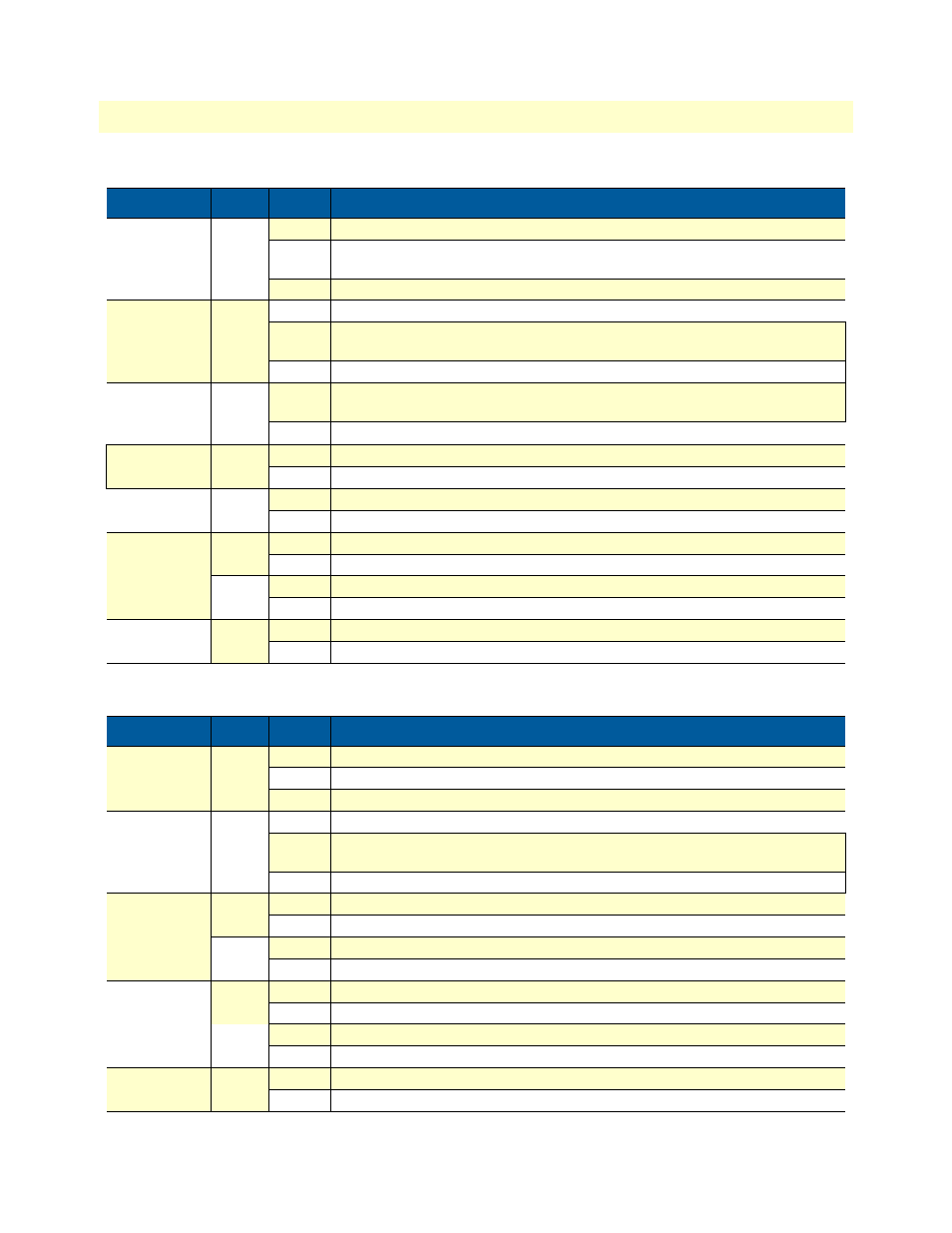
Hardware overview
Table 4. Rear-panel LED indicators
TEST MODE
Green On solid One or more Ethernet ports or the STM-1 port is in test mode.
Flashing One or more Ethernet ports or the STM-1 port is in test mode and errors have been
received.
Off
None of the ports is operating in test mode.
WAN
Green On solid Indicates the STM-1 port is activated, synched, and operating normally.
Flashing Indicates that the STM-1 port is detecting the SDH network, but is unable to synchro-
nize with it.
Off
Indicates rear blade not present or STM-1 port is not configured
ENET(SWITCH)
Green On solid Indicates there is Ethernet frame activity on at least one of the eight PICMG 2.16 connec-
tions to other blades on the PSB bus.
Off
No Ethernet frame activity detected on the PICMG 2.16 bus.
ENET(REAR)
Green
On
Indicates Ethernet frame activity on one or both of the 10/100/1000 Ethernet ports
Off
There is NO Ethernet frame activity on either of the 10/100/1000 Ethernet ports
ON LINE
On
Reserved for future use
Off
Reserved for future use
10/100 ENET
Green
On
Ethernet Link is established
Integrated LEDs
Off
No Ethernet link is established
on RJ-45
Yellow
On
Flashes to indicates Ethernet frame activity on this port
Connector
Off
Indicates no Etherent frame activity on this port
READY
Blue
On
Card ready for removal from cPCI chassis.
Off
Card not ready for removal from cPCI chassis.
LED
Color Status
Meaning
ALARM
Red
On solid A minor alarm condition has been detected.
Flashing A major alarm condition has been detected
Off
The Model 6511RC is operating normally.
WAN
Green On solid Indicates the STM-1 port is activated, synched, and operating normally.
Flashing Indicates that the STM-1 port is detecting the SDH network, but is unable to synchro-
nize with it.
Off
Indicates rear blade not present or STM-1 port is not configured
ENET 1
Green
On
Ethernet Link is established
Integrated LEDs
Off
No Ethernet link is established
on RJ-45
Yellow
On
Flashes to indicates Ethernet frame activity on this port
Connector
Off
Indicates no Etherent frame activity on this port
ENET 2
Green
On
Ethernet Link is established
Integrated LEDs
Off
No Ethernet link is established
on RJ-45
On
Flashes to indicates Ethernet frame activity on this port
Connector
Off
Indicates no Etherent frame activity on this port
Ready
Blue
On
Card ready for removal from cPCI chassis.
Off
Card not ready for removal from cPCI chassis.
Table 3. Front-panel LED indicators (Continued)
LED
Color Status
Meaning