0 led status monitors, Led status monitors – Patton electronic 1194 User Manual
Page 18
18
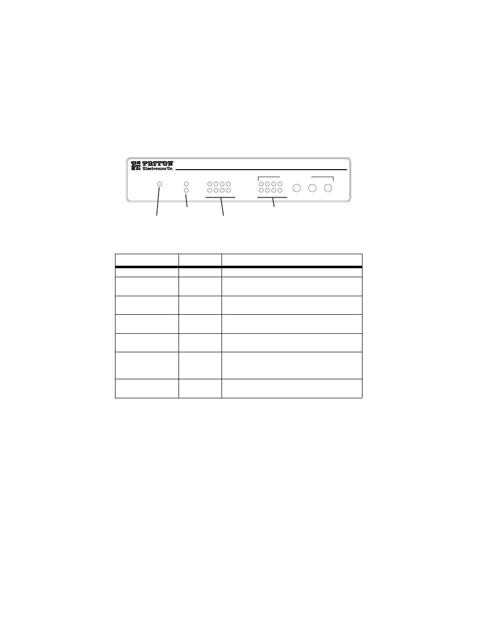
6.0 LED STATUS MONITORS
The Model 1194 features front panel LEDs that monitor power, network,
fiber, and diagnostic signals. Figure 10 shows the front panel location of
each LED. Table 3 describes each LED’s function.
Figure 10.
Front panel picture of 1194
Table 3:
Front panel LED descriptions
LED
LED color
Description
POWER
Green
Indicates the presence of AC or DC power
FIBER LINK
Green
Indicates the unit fiber link is synchronized
and operating correctly
FIBER NS
Red
Indicates the absence or synchronization
or fiber connection
Network Link (4)
Green
Indicates synchronization of the corre-
sponding E1 or T1 port (P1-P4)
Network Loss (4)
Red
Loss of synchronization or link of the cor-
responding E1 or T1 port (P1-P4)
Test Mode TM (4)
Yellow
Indicates the activation of Local, Remote,
or 511/511 pattern for corresponding E1
or T1 port (P1-P4)
Error ERR (4)
Red
Indicates the presence of errors in test
pattern data received
511
G.703/G.704 Test Modes
P3
P1
511E
P4
P2
TM
ERR
P4
P3
P2
P1
P4
P3
P2
P1
G.703/G.704
Fiber
Link
NS
Link
NS
Model 1194E Single Mode Fiber - Quad G.703/G.704 Modem
Power
Diagnostics LEDs
Network LEDs
Fiber LEDs
Power LED