0 configuration, 1 configuring the hardware dip switches, Configuration – Patton electronic 1194 User Manual
Page 10: Configuring the hardware dip switches, Link ns link ns, S1 s2
10
3.0 CONFIGURATION
The Model 1194 has 16 DIP switches that enable configuration of the unit
for a wide variety of applications. This section describes location of the
switches and explains the different configurations.
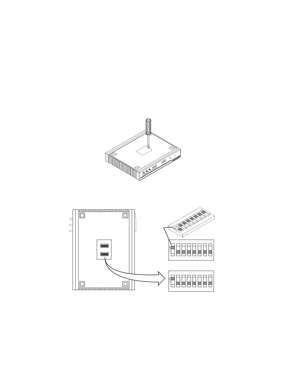
3.1 CONFIGURING THE HARDWARE DIP SWITCHES
Using a small flat-tip screwdriver, remove the protective cover located on
the underside of the Model 1194 (see Figure 3).
Figure 3.
Removing the cover to access DIP switches S1 and S2
Figure 4 shows the orientation of the DIP switches in the “ON” and “OFF”
positions.
Figure 4.
DIP switches S1 and S2
511
G.703/G.704 T
est
Modes
P3
P1
511
E
P4
P2
TM
ERR
P4
P3
P2
P1
P4
P3
P2
P1
G.703/G.704
Fiber
Link
NS
Link
NS
Mod
el 1
194
E S
ing
le
Mod
e F
ibe
r -
Qua
d G
.70
3/G
.70
4 M
ode
m
Po
we
r
511
G.703/G.704 T
est
Modes
P3
P1
511
E
P4
P2
TM
ERR
P4
P3
P2
P1
P4
P3
P2
P1
G.703/G.704
Fiber
Link
NS
Link
NS
Mod
el 1
194
E S
ing
le
Mod
e F
ibe
r -
Qua
d G
.70
3/G
.70
4 M
ode
m
Po
we
r
1 2 3 4
ON
5 6 7 8
Push toggle up
for ON position
Switch toggle
Push toggle
down for
OFF position
1
2
3
4
ON
5
6
7
8
S1
1 2 3 4
ON
5 6 7 8
S1
S2
1 2 3 4
ON
5 6 7 8
1 2 3 4
ON
5 6 7 8
S1
S2