Switches s1-2 and s1-3: line build out, Switches s1-6 and s1-7: clock mode – Patton electronic 1194 User Manual
Page 12
12
tions and decodes them as zeros. This method enables the network to
meet minimum pulse density requirements.
•
Bipolar 8 Zero Substitution (B8ZS
): This mode assures proper bit
density in the data stream. In this mode any data pattern can be trans-
mitted without causing ones density errors. This mode allows for 64
kbps clear channel timeslots.
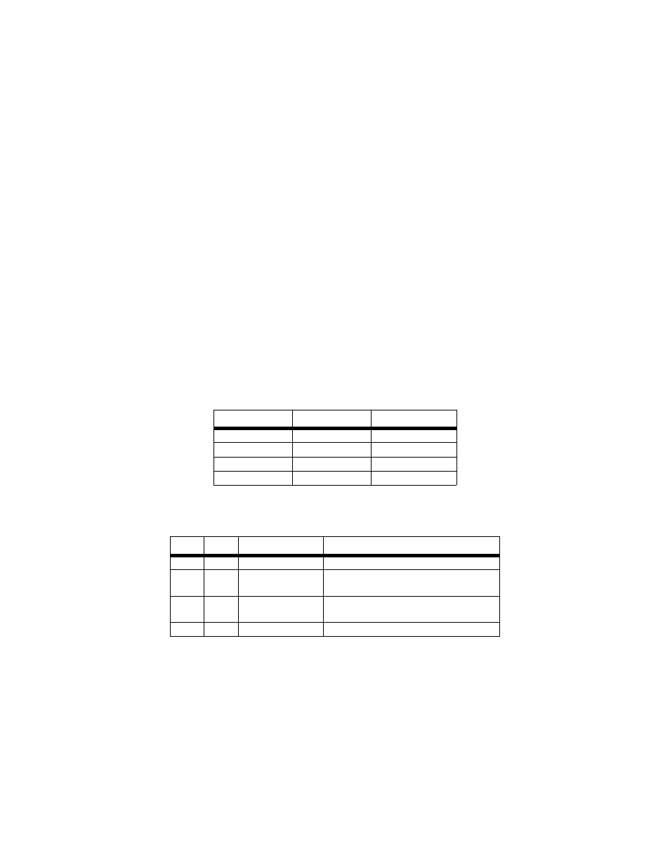
Switches S1-2 and S1-3: Line Build Out.
Line buildout (LBO) is a T1
equipment feature, it controls the transmitter signal strength and pulse
shape sent over the T1 line. For most applications, the default settings (0
dB) will suffice. When connecting to a carrier’s T1 circuit, the carrier will
determine what LBO is necessary. 0 dB provides the highest signal
strength, and therefore the longest distance, while -15.0 dB provides the
lowest usable signal level. -22.5 dB is used to test the line and should not
be used in normal applications.
Transmitted E1 signals are not specified in terms of LBO. Patton’s Model
1194/E1 complies with ITU-T G.703 recommendation for signal pulse
shape and amplitude, and has a reach of 1.6 km. No user configuration
is required
Switches S1-6 and S1-7: Clock Mode.
Use switches S1-6 and S1-7 to
determine clock mode of the 1194.
Note
The Model 1194 units are intended to work in pairs. Set the
clock modes for the Model 1194 units with one end of the link set
for receive recover and the other end set for either internal or
network.
S1-2
S1-3
Function
ON
ON
0dB
OFF
ON
-7.5dB
ON
OFF
-15.0dB
OFF
OFF
-22.5dB
S1-6
S1-7
Setting
Description
ON
ON
Internal
Transmit clock generated internally
ON
OFF
Receive
Recover
Transmit clock derived from the fiber
line link
OFF
ON
Network
Transmit clock derived from E1 or T1
equipment interface
OFF
OFF
Internal use only