Powerware 685 User Manual
Page 30
24
Powerware 9350 Series 685 and 1085 Auxiliary Battery Cabinets
Installation Manual
164201408 Rev. P00 053002
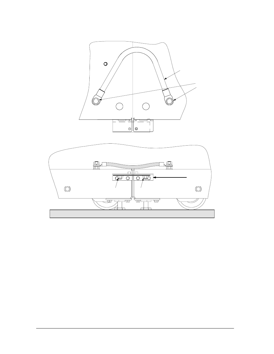
Existing
Front of
Battery Cabinet #2
Bracket from kit
Nut from kit
Nut from kit
hinge
Front of
Battery Cabinet #1
Ground
Wire
Ground
Studs
Figure 17. Connecting Two Series 1085 Bases
3.
Locate the large flat bracket from the field kit. Place the bracket over the stud
on the bottom side of battery cabinet #1 lower hinge, and over the stud on the
bottom side of battery cabinet #1 lower hinge. Attach the bracket with two M8
self-locking nuts from the field kit (see Figure 17).
4.
Locate the ground wire from the field kit. Route the ground wire from the
customer ground stud in battery cabinet #1, under the lower right-hand battery
tray, into the cable access area in battery cabinet #2, and attach to customer
ground stud. Hardware is provided on each ground stud.
5.
Repeat Steps 1 through 4 to join additional Series 1085 Battery Cabinets
together.