Channel box test commands, 4 channel box test commands – Panasonic EB-GD30 User Manual
Page 42
TEST AND MEASUREMENT
Issue 1
Section 6
MCUK991001C8
Revision 0
– 36 –
Service Manual
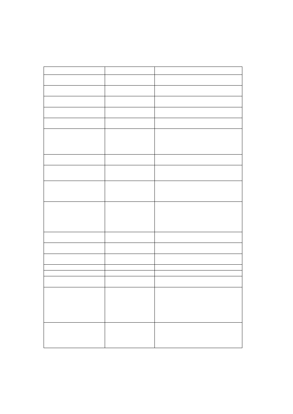
6.4 Channel Box Test Commands
The following table outlines the commands available using the channel-box software.
After the handheld unit has been switched on (section 7.3), use the up/down scroll keys on the personal computer keyboard to
select the channel-box command. Use the left/right scroll keys to display the required indication and press the ENTER key to
select the displayed function.
CHANNEL BOX COMMAND
INDICATION
FUNCTION
TEST MODE
Terminates test mode.
Restarts test mode
INITIALIZE
When RETURN is pressed this will reset the
default channel settings.
CHANGE CH GSM
Sets up predefined channel settings for GSM
frequencies.
CHANGE CH DCS
Sets up predefined channel settings for DCS
frequencies.
POWER LEVEL
Allows a specified power level to be set at the
UUT.
TX DATA
Sets TX Modulation to
Normal burst DATA all 0s
Normal burst DATA all 1s
Normal burst DATA all random
Access burst DATA random
RSSI (DBM)
Provides an RSSI reading on the User specified
channel.
SET AGC 1
SET AGC 2
SET AGC 3
Allows changes to AGC levels on LOW,
MIDDLE, HIGH channels.
SP LOOP BACK
Provides an audio path for use with the GSM
test station
Sets audio loop-back from TX audio to RX audio
without processing by the CODEC
PATH CONT
Sets audio paths:
MIC off speaker off
MIC external speaker internal
MIC external speaker external
MIC internal speaker internal
MIC internal speaker external
VOL. BUZZ
Sets buzzer volume between values
0 to 3 (Min to Max)
VOL. SIDE
Sets 4 side tone volume levels between
0dB and -18dB
VOL. MIC
Sets 8 MIC volume levels between
26dB and 40dB
VOL. SP1
Sets speaker pre-amp volume levels
VOL. SP2
Sets speaker volume levels
GET KEY CODE
Displays the value of a key pressed on the
keypad
CONTROL OUT
Switches on Incoming LED
Switches on Backlight LEDs
Switches charge sequence on LCD
Switches on Charging LED
Switches on handsfree mode
Switches off all above
Switches on all above
CHECK LCD1
Provides 50% visual display of check pattern on
the UUT LCD
Provides 50% visual display of check pattern on
the UUT LCD