2 rssi – Panasonic EB-GD30 User Manual
Page 48
TEST AND MEASUREMENT
Issue 1
Section 6
MCUK991001C8
Revision 0
– 42 –
Service Manual
Power levels between PL15 and PL10.
Power level PL0 (limits ±0.2dB).
6.5.2 RSSI
This procedure describes the calibration of RSSI on the compensation channel (Mch = Ch 67). This process must be carried
out for LOW/BOTTOM CHANNEL and HIGH/TOP CHANNEL. The following channel settings are used in this procedure:
1.
Set up the test equipment as described in Section 6.3 and switch the unit into test mode as described.
2.
Apply a carrier frequency of +68KHz to the UUT (for Ch 67 = 948.400 MHz) at an input level of -90 dBm.
3.
At the Channel box highlight the CHANGE CH <67> field and press ENTER.
4.
Highlight the SET AGC 1 field and change the set value to 45 dB and press ENTER.
5.
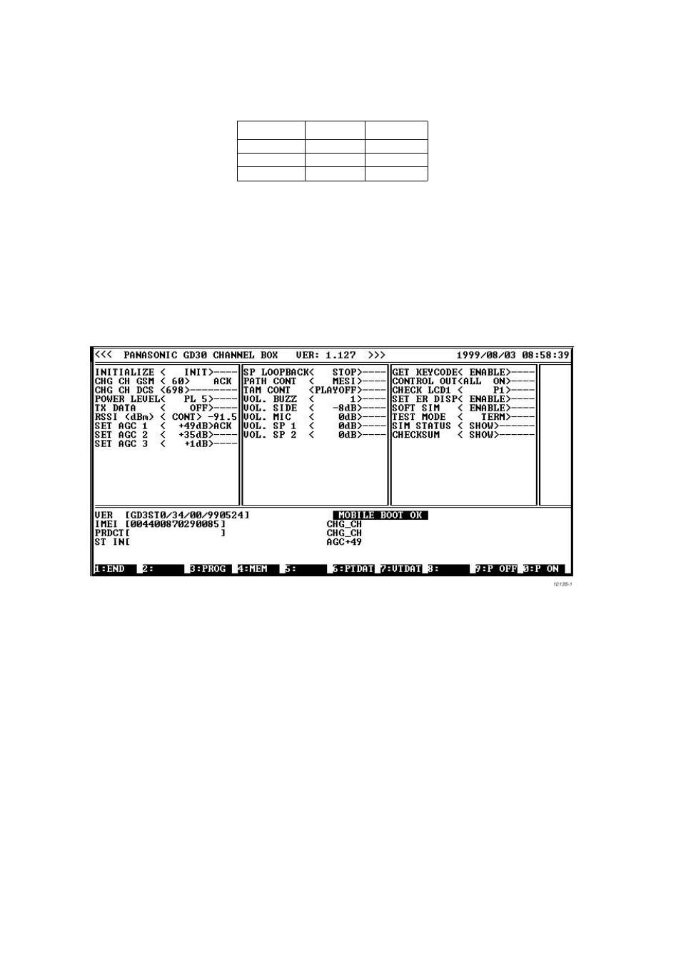
Highlight the RSSI dBm <> field and press ENTER.
Figure 6.20: RSSI dB field
6.
If the measured value is not -90 ±1 then make the following calculation:
RSSI offset value = [-(90+MEASURED RSSI VALUE)] x 2
= [-90-MEASURED RSSI VALUE] x 2,
for example
[-(90+(-95))] x 2
= [-90-(-95)] x 2
= 10
Record the result.
Channel
GSM900
GSM1800
Low/Bottom
10
544
Mid
62
699
High/Top
105
885