Charging calibration – Panasonic EB-GD30 User Manual
Page 58
TEST AND MEASUREMENT
Issue 1
Section 6
MCUK991001C8
Revision 0
– 52 –
Service Manual
Charging Calibration
NOTE:
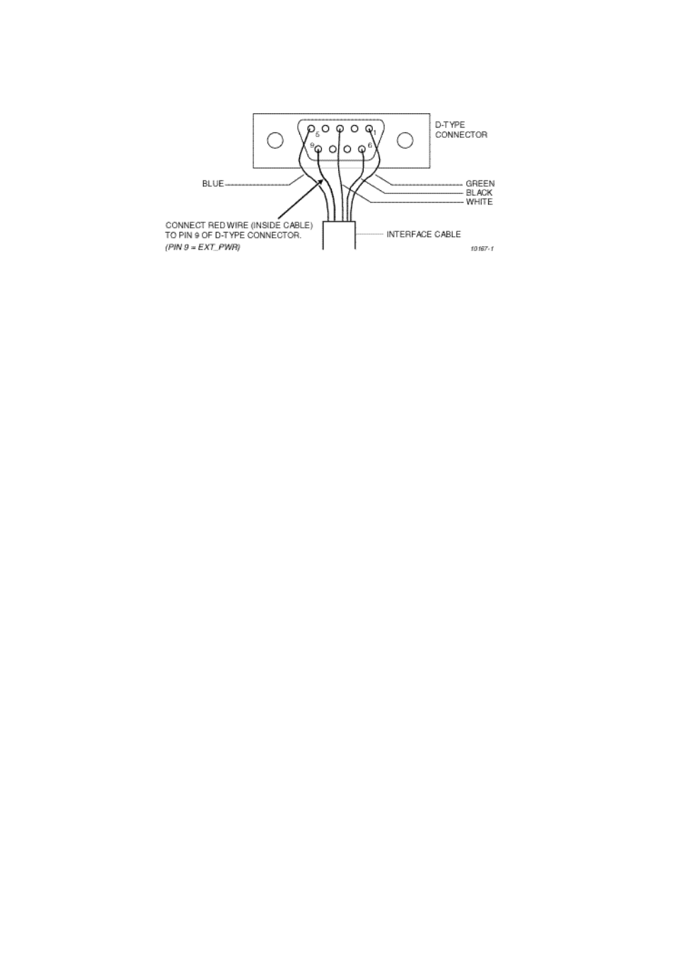
The charging calibration procedure requires an interface cable (part number JT00004), modified as shown in the
diagram below, to allow EXT_PWR to be fed via pin 9 of the D-TYpe connector to the phone connector.
Figure 6.33: Modification to Interface Cable JT00004
1.
Ensure that the BCVCU output is set to 4.1 V output and the MODE or EXT_PWR switch set to ON. Set the 82 Ohms
switch ON.
2.
Press {shift}+[F4].
3.
Go to, and select: "Set DAC Data". Type a value of 714, [enter].
4.
Using arrows
↑↓
, highlight "Control out". Use
←→
arrows to highlight and select "CRG ON". (“ACK” should be displayed
on the PC screen. If it is not displayed, then it may be necessary to re-power the telephone and start the Charging
Calibration procedure again from step 1.)
5.
Disconnect VBAT by switching the BCVCU output to OFF.
6.
Measure VBAT voltage at the test battery. If the voltage is inside the range 4.1 V ± 5 mV then go to step 11 below.
Otherwise, calculate the difference thus:- (measured voltage - 4.1)/0.0057 = difference.
For example, for a measured voltage of 4.08 V the difference will be: (4.08 - 4.1) / 0.0057 = -3.5
7.
Press {shift} + [F4].
8.
Go to, and select: "Set DAC Data". Enter the value calculated by subtracting the difference value recorded in step 6 from
the DAC Data value (714). This value must be an integer.
As an example, the example from step 6 would produce a value of: 714 - (-3.5) = 717.5 or 718 .
9.
Repeat steps 6 to 8 until the measured voltage is 4.1 V ± 5 mV
10. If the final value for DAC Data is outside the range 614 ± 814, then there is a fault and further investigation is required.
Otherwise store the value as described below.
11. Press [F6]; Go to, and select:- "Trim Other";
12. Go to, and select:- "DAC Reference"; Enter the final DAC data value from step 10.
13. Press {shift}+[F4].
14. Go to, and select:- "Set DAC Data".
15. Enter:- (value stored in step 12) - 200.
16. Press [F4].
17. Go to, and select:- View ADC lines.
18. Read value for ADIN1 ("BAT VOLT").
19. If ["BAT VOLT HIGH" (from Voltage Calibration, step 5) - value read above], is inside the range 255 - 171, then go to
step 20 (below) to store value. Otherwise there is a fault and further investigation is required.
20. Press [N] (in repeat yes/no box), then [enter]. Press [F6]; Highlight and select "Trim Other".
21. Highlight and select "DAC Step".
22. Enter value obtained in step 19.
23. Press {shift}+[F4].
24. Select: "Set DAC Data".
25. Re-enter original value from step 10 (i.e. present value +200).
26. Press [F4].
27. Highlight, and select:- "View ADC Lines".
28. Read ADIN5 (CRG CURRENT) value and record it as "Total current".
29. On the BCVCU, set the 82 Ohm switch to OFF.