2 led indication – Liebert UPS System User Manual
Page 50
Chapter 5 Operation of Display Panel
44
2001-11-08
UL33-0400L
12:50:30
Д ж
± д¿ ªЖф
² ¢» ъМ ¨К э 2/4
П аµ зС ¹ V
µ з Б ч A
Жµ
В К
Hz
A(B)
B(C) C(A)
221
11.8
12.3
50.2 50.1
50.1
0.99
0.99
К дИ л¿ Х
¿ ª± Õ
º П
11£ -08 12:09
К д³ ц¿ Х
¿ ª± Õ
º П
Ц чВ ·Д ж
± д¹ ©
µ ç
µ з³ Ш
¾ щ³ д
11£ -08 12:09
11£ -08 12:09
11£ -08 12:15
11£ -08 12:12
F1
F2
F3
F4
Emergency
shutdown
Inverter
stare
Inverter
stop
Fault
clearing
Mute
Ц чВ ·К дИ л
Е Ф
В ·К дИ л
½ »Б чК д³ ц
± ¾
» ъ¸ ºФ Ш
² ¢» ъ¸ ºФ Ш
µ з³ Ш
К э¾ Э
¹ ¦В К
Т тК э
П Я
µ çÑ ¹ V
220
221
381
380
382
Battery
indicator
Bypass
indicator
Inverter
indicator
Load
indicator
Rectifier
indicator
Alarm
indicator
Alarm
2001-11-08
UL33-0400L
12:50:30
Inv. On
Units 2/4
ID: 1
Input Breaker Closed
11£ -08 12:09
UPS in Battery Mode
Battery low
11£ -08 12:09
11£ -08 12:28
11£ -08 12:28
11£ -08 12:50
Records
Out
System
Local
Settings
Byp. Breaker Closed
Mains Volt. Abnormal
Battery
Chinese
Chinese English
Com. Adress Set
1
1
Date & Time Set
2001£ -11£ -08 12:50:30
Language
m
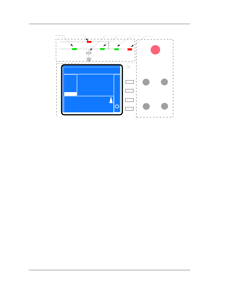
Fig. 5-2 Function Dividing
5.1.2 LED Indication
There are six LEDs to indicate the operation state and fault.
Yellow – Normal
Red – Fault condition
Bypass LED
Yellow – Load on Bypass power
Red – Bypass Voltage out of normal range
Off – Bypass Normal
Rectifier LED
Yellow – Load on Rectifier
Flashing Yellow – Utility Normal, but rectifier not operating
Red – Rectifier fault
Off – Utility abnormal
Battery LED
Green – Battery powers the load