Maintenance, Inspect ignition and flame sense electrodes, Check ignition ground wiring – Lochinvar Shield SNA285-125 User Manual
Page 56: Check all water heater wiring, Check control settings, Perform start-up and checks, Check burner flame, Check flame signal, Review with owner
56
12
Maintenance
Inspect ignition and flame sense
electrodes
1. Remove the ignition and flame sense electrodes from
the water heater heat exchanger access cover.
2. Remove any deposits accumulated on the
ignition/flame sense electrode using sandpaper. If the
electrodes cannot be cleaned satisfactorily, replace with
new ones.
3. Replace ignition/flame sense electrode, making sure
gasket is in good condition and correctly positioned.
Check ignition ground wiring
1. Inspect water heater ground wire from the heat
exchanger access cover to ground terminal strip.
2. Verify all wiring is in good condition and securely
attached.
3. Check ground continuity of wiring using continuity
meter.
4. Replace ground wires if ground continuity is not
satisfactory.
Check all water heater wiring
1. Inspect all water heater wiring, making sure wires are in
good condition and securely attached.
Check control settings
1. Set the control module display to Parameter Mode and
check all settings. Adjust settings if necessary. See
Section 1 of this manual for adjustment procedures.
2. Check settings of external limit controls (if any) and
adjust if necessary.
Perform start-up and checks
1.
Start water heater and perform checks and tests
specified in Section 10 - Start-up.
2.
Verify cold fill pressure is correct and that operating
pressure does not go too high.
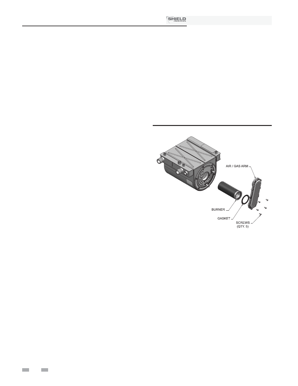
Check burner flame
1.
Inspect flame through observation window.
2.
If the flame is unsatisfactory at either high fire or low fire,
turn off water heater and allow water heater to cool down.
Remove the burner and clean it thoroughly using a
vacuum cleaner or compressed air. Do not use
compressed air to clean burner if performed inside a
building.
3.
Remove the burner, reference FIG. 12-2 below.
4.
When replacing the burner, ensure gasket is in good
condition and positioned correctly (FIG. 12-2).
Figure 12-2 Burner Assembly
Check flame signal
1. At high fire the flame signal shown on the display should
be at least 10 microamps.
2. A lower flame signal may indicate a fouled or damaged
flame sense electrode. If cleaning the flame sense
electrode does not improve, ground wiring is in good
condition, and ground continuity is satisfactory, replace
the flame sense electrode.
3. See Section 3 - Troubleshooting for other procedures to
deal with low flame signal.
Review with owner
1. Emphasize the need to perform the maintenance schedule
specified in this manual.
2. Remind the owner of the need to call a licensed
contractor should the water heater or system exhibit any
unusual behavior.
Installation & Service Manual
TM