Determine water heater location – Lochinvar Shield SNA285-125 User Manual
Page 12
1
Determine water heater location
12
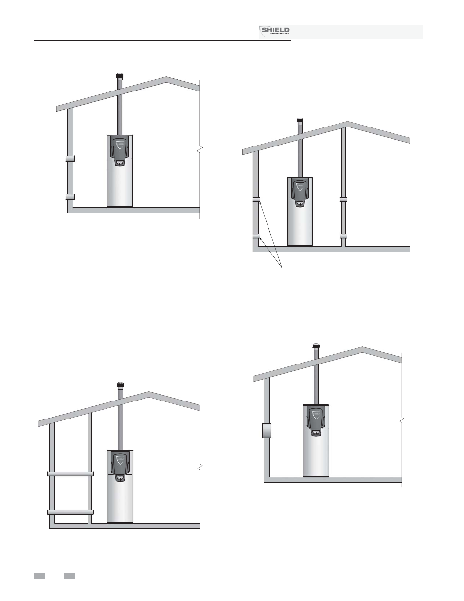
Figure 1-3_Combustion Air Direct from Outside
1.
If air is taken directly from outside the building
with no duct, provide two permanent openings to
the equipment room (see FIG. 1-3):
(a) Combustion air opening, with a minimum free
area of one square inch per 4000 Btu/hr input
(5.5 cm
2
per kW). This opening must be
located within 12" (30 cm) of the bottom of the
enclosure.
(b) Ventilation air opening, with a minimum free
area of one square inch per 4000 Btu/hr input
(5.5 cm
2
per kW). This opening must be
located within 12" (30 cm) of the top of the
enclosure.
Figure 1-4_Combustion Air Through Ducts
2.
If combustion and ventilation air is taken from the
outdoors using a duct to deliver the air to the
equipment room, each of the two openings should be
sized based on a minimum free area of one square inch
per 2000 Btu/hr (11 cm
2
per kW) of input (see FIG. 1-4).
Figure 1-6_Combustion Air from Outside - Single
Opening
3.
If air is taken from another interior space, each of the
two openings specified above should have a net free
area of one square inch for each 1000 Btu/hr (22 cm
2
per kW) of input, but not less than 100 square inches
(645 cm
2
) (see FIG. 1-5).
4.
If a single combustion air opening is provided to bring
combustion air in directly from the outdoors, the opening
must be sized based on a minimum free area of one square
inch per 3000 Btu/hr (7 cm
2
per kW). This opening must
be located within 12" (30 cm) of the top of the enclosure
(see FIG. 1-6).
IF NECESSARY FOR
TIGHT CONSTRUCTION
Figure 1-5_Combustion Air from Interior Space
Installation & Service Manual
TM