Calibrate the gyro as described in, Calibrating the, Calibrating the gyros – Lennox Hearth G8 User Manual
Page 103
Calibrating the Gyros
To calibrate the azimuth, elevation, and roll gyros, follow the
steps below.
1. With a PC connected to the MCU’s maintenance
port, apply power to the antenna unit.
2. Type
HALT
> (
return/ENTER key) while the system is performing
the limit switch initialization routine. The system
will complete the initialization function by finding
the azimuth and elevation switch limits and then
go to the home position.
3. Type
DEBUGON
to enter the Debug Mode.
4. Type
EL,300
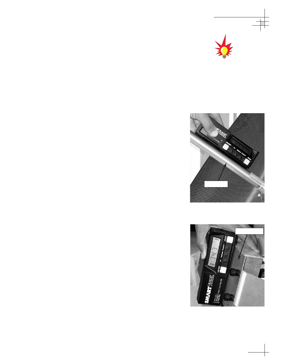
5. Using a digital level (or equivalent), measure and
record the angle of the feed tube, as shown in
Figure 5-19.
6. Type
=CALUP,XX.X
, where XX.X is the
number you recorded in Step 5.
7. Using a digital level, measure and record the angle
of the roll gyro on the PCB module, as shown in
Figure 5-20.
8. Type
GYROANGLE,X.XX
, where XX.X is the
number you recorded in Step 7.
9. Type
=CALGYRO
Verify that the Antenna
Gyro Azimuth scale factor is between -0.00090 and
-0.00110 and the Antenna Gyro Elevation scale
factor is between 0.00090 and 0.00110.
10. Type
ZAP
to restart/reinitialize the system.
Maintenance
54-0198
105
complete details on connecting a
PC to the system via the
maintenance port.
Figure 5-19
Measuring Feed Tube Angle
Figure 5-20
Measuring Roll Gyro Angle
Feed Tube
PCB Module