Figure 5-15 pcb module connectors, Bottom top – Lennox Hearth G8 User Manual
Page 100
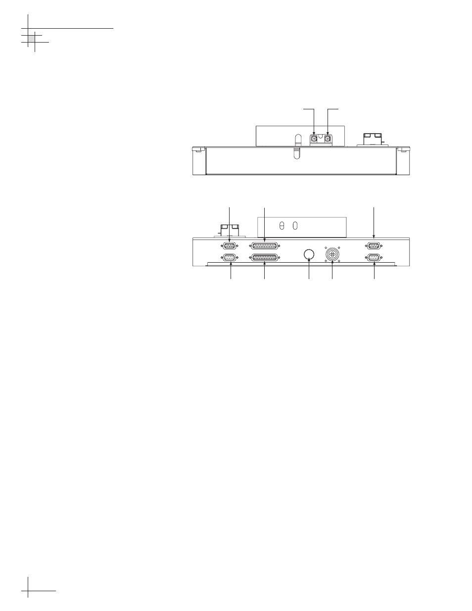
11. Reconnect the cables that you removed in Steps 2
and 3. Be sure to reconnect all cables in their proper
positions. Figure 5-15 shows the proper connector
assignments.
54-0198
102
TracVision G8 Owner’s Manual - Guide to Technical Information
POWER
ELEVATION GYRO
INTERNAL SENSOR
SKEW MOTOR
ELEVATION & AZIMUTH MOTORS
AZIMUTH/ROLL GYRO
LIMIT SWITCHES
FUSE
Limit
Switches
Internal
Sensor
Azimuth/Roll
Gyro
Elevation
Gyro
Power
Elevation & Azimuth
Motors
Skew Motor
Fuse
From LNB
BOTTOM
TOP
To IRD
Figure 5-15
PCB Module Connectors