S ca le la ser 2 0 0 a r f – Lanier LASER 200 User Manual
Page 7
LANIER
– 1 /3
rd
S ca le La ser 2 0 0 A R F -
INSTRU CTIO NS
© 2002 Lanier R/C
Page -7
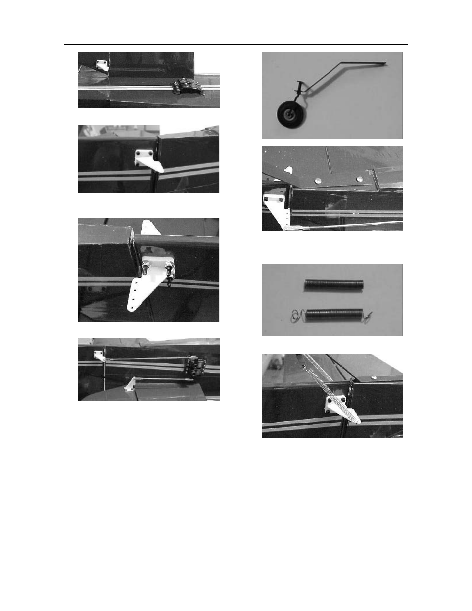
37. U se a straight edge to align the elevator and
rudder control horns location.
38. Install the horns on the elevator halves w ith (4)
4-40 screw s in each horn going through to the
backing plate.
39. Install the rudder horns by securing them w ith
(4) 4-40 screw s and (4) nylon lock nuts.
40. Install your servo arm s (D ubro heavy duty, not
included) on the servos.
41. Trial fit the 4-40 rods and clevis on the servos
and horns, the 5 1/2” rods are for
the
elevator
halves,
the 10” rods are for the rudder. Tw o solder
clevis are used
on the rudder rods. Trim
the
rods
to length as needed. W hen the lengths are
determ ined
and
all
surfaces
are
centered,
lock
the
clevis on the rod w ith locktite. (Y ou can also
solder one clevis in position if you w ant to be
very secure ) A lso install the clevis keepers on
the clevis pins.
42. Locate the tail w heel bracket and parts.
43. Fasten the tail bracket at the rear of the fuse w ith
tw o #6 ½
screw s. D rill tw o 3/32” pilot holes
before installing. Install so the angle is aligned
w ith the edge of the vertical stabilizer.
.
44. Locate the springs for the tail, and prepare the
ends by bending a loop on each end.
45. Install a spring on each side of the rudder.
Shorten the springs if needed to put even tension
on the arm s and keep the axle centered.