S ca le la ser 2 0 0 a r f – Lanier LASER 200 User Manual
Page 16
LANIER
– 1 /3
rd
S ca le La ser 2 0 0 A R F -
INSTRU CTIO NS
© 2002 Lanier R/C
Page -16
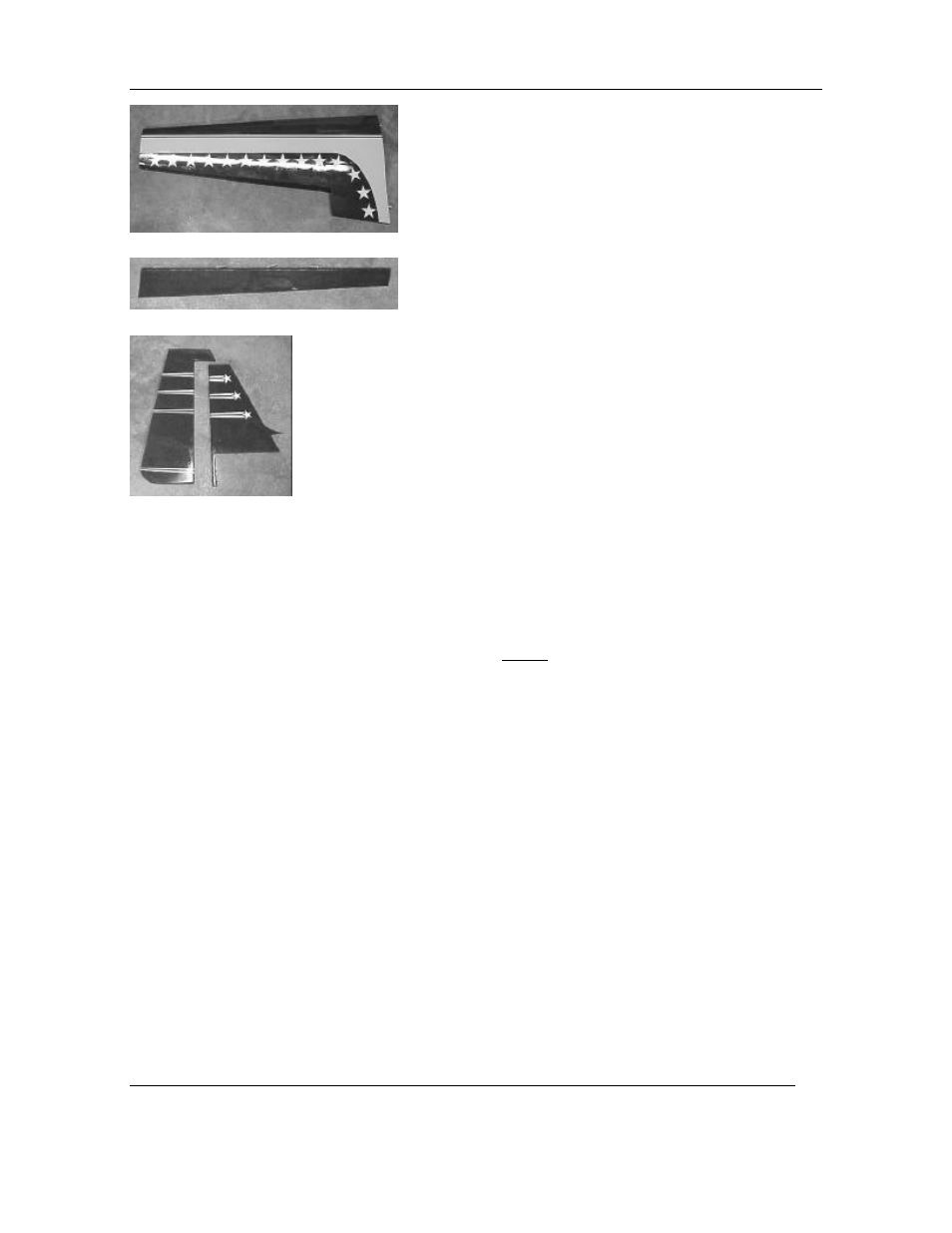
W ing halves
A ilerons
Rudder and V ertical stab
H A R D W A R E LIST
W ings
2
H D adjustable control horn
2 2& 7/8" 4-40 threaded rods
2
6-32 x 1" cap screw
10
large hinge points
8
#4 x 1/2 sheet m etal screw
4
4-40 clevis
Tail
13
large hinge points
4
large t style horns (included)
12
4-40 x 3/4 cap screw
4
4-40 nylon lock nuts
2
10" 4-40 threaded rod
2
5 1/2" 4-40 threaded rod
6
4-40 clevis
2
Solderclevis
2
#6 x 3/4" pan head screw
1
1-1/4 tail w heel
1
O hio superstar tail w heel braket
2
1/8" w heel collars
12
tail brace brackets
8
18" 2-56 threaded one end rod
8
2-56 clevis
8
nylon L connectors
1
2"x3/4" alum inum pl
ate w ith 5 holes,
#6 size in center, 3/32 in 4 corners
6
4-40 x 3/4 cap screw
6
4-40 nylon lock nuts
Cowl
2
4 x 20m m round head screw s
2
4
x
20m m flat head screw
1
24 oz fuel tank
2
Large nylon cable ties
Engine m ount
4
10-32 x 1-1/2 cap screw
8
#10 w asher
4
10-32 nylon lock nuts
1
12" 2-56 rod
1
2-56 clevis
1
ez connector
Landing gear
4
4 x 22m m round head screw s
4
4m m w asher
2
4-40 blind nuts
2
248 3/16 axle
2
4" w heel
2
4-40 x 1/2 cap screw
2
#4 w asher
1
A lum inum landing gear
Canopy
4
3 x 20m m flat head screw
ADDITIO NAL EQ UIPM ENT NEEDED TO
C O M PLETE Y O U R 1/3
rd
LA SER A R F
G eneral
3.2 – 4.2 2 stroke R/C engine and m uffler
G as fuel line
M inim um of 4 chan. radio set req. w ith (7) servos
30 m inute Z-poxy
M edium Zap CA (green)
Thin Zap CA (pink)
Zap a dap goop
(1) radio foam
Tru Turn 4” spinner
6/32 tap
3M vinyl tape
W illiam s Bro. Pilot figure