Kathrein MSK 125 User Manual
Page 30
30
SAT
39
Write N1
Set port group 1
1
3A
Write N2
Expansion option
1
3B
Write N3
Expansion option
1
40
Read A0
Read analogue value A0
-
41
Read A1
Read analogue value A1
-
48
Write A0
Set analogue value A0
1
49
Write A1
Set analogue value A1
1
4F
Write A7
Set analogue value A7
1
50
LO string
Read current frequency
-
51
LO now
Read current frequency (table entry number)
-
52
LO Lo
Read Lo frequency (table entry number)
-
53
LO Hi
Read Hi frequency (table entry number)
-
58
Write Freq
Write channel frequency
2 or 3
59
Ch.No.
Set selected channel number (receiver)
2
60
Halt
Stop positioner
-
61
Go E
Move positioner eastward
-
62
Go W
Move positioner westward
-
64
P Status
Read positioner status register
-
65
Read Pos
Read positioner counter
-
6C
Goto
Move positioner motor to “Counter value”, Hi, Lo
2
6D
Write Pos
Set positioner counter, Hi, Lo
2
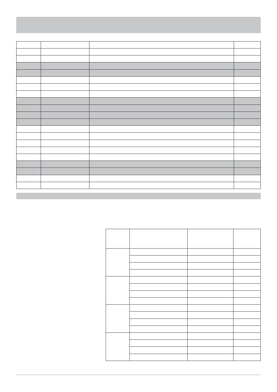
COMMAND OVERVIEW FOR DATA BYTE
An appropriate data byte must only be sent id the command byte
requires data bytes. This can be seen in the above command byte
table. For more information on which data byte to send to which
command byte please refer to the specifi cation of the device used.
Orbit
position
Polarisation
Switch Position
H/V
Switch Position
Low Band
Data Byte
1
V
Lo
F0
V
Hi
F1
H
Lo
F2
H
Hi
F3
2
V
Lo
F4
V
Hi
F5
H
Lo
F6
H
Hi
F7
3
V
Lo
F8
V
Hi
F9
H
Lo
FA
H
Hi
FB
4
V
Lo
FC
V
Hi
FD
H
Lo
FE
H
Hi
FF