Slant/Fin V-33 User Manual
Page 5
V
ICTORY
5
HORIZONTAL PRESSURE VENTING
All VICTORY models are certified for horizontal pressure
venting with the following restrictions:
1.
Vent Material
A. The vent system for horizontal venting must be UL list-
ed single wall Saf-T 3" diameter #AL 29-4C
▲
stainless
steel manufactured by Heat-Fab, Inc. The manufactur-
ers’ part numbers for various items of the vent system
are listed in SLANT/FIN Parts List, Publication # V-
10PL.
B. DO NOT use plastic or galvanized flue pipe.
C. For horizontal, through the wall venting, the 3" flue
collar and adapter MUST be used. The vent pipe size
must be 3" diameter from the boiler to the outside ter-
mination. Certain restrictions on the location of the
vent terminal are specified in APPENDIX "B" and must
be followed.
2
. Installation
A. Figures 7 and 8 show the allowed venting arrange-
ments. The maximum equivalent vent length is 40 feet
plus vent terminal for all models except V-180 which
has a 20 feet maximum equivalent vent length. Every
90° turn in the vent piping is equivalent to 5 feet of
straight run, (eg. a V-120 system with 3 elbows and the
outside terminal would allow 40 - 15 = 25 feet of
straight run). The minimum allowable equivalent vent
length is 2 feet and 1 elbow plus vent terminal for all
models, see table below. NOTE: For best operation,
elbows should be at least five diameters apart other-
wise maximum vent length should be reduced.
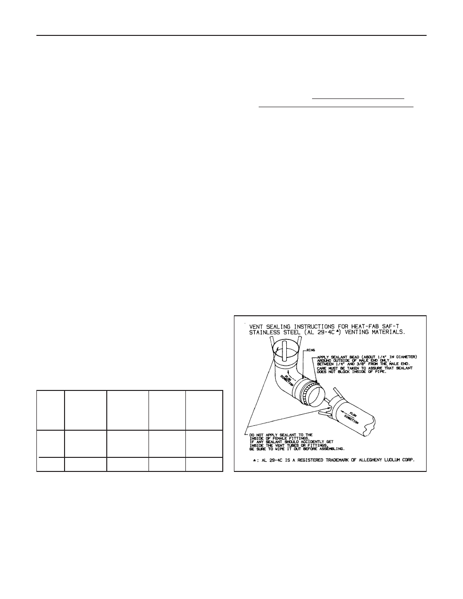
B. When joining the various components of the above list-
ed vent systems, the manufacturers’ instructions
should be closely followed to insure proper sealing.
Use GE-RTV 106 or Dow Corning 732 Sealant for
sealing of pipe and fittings. See figure 4 for proper
application of vent pipe sealant.
C. All Victory boilers require a condensate drain and drain
trap.
The horizontal pipe must be sloped TOWARD the con-
densate drain at least 1/4" per 1' of run. The horizontal
portion must also be supported with pipe straps at
intervals no greater than indicated by vent pipe manu-
facturer’s instruction.
Where the vent pipe goes through the outside wall, a
thimble must be used (see Figures 7 and 8).
Heat-Fab pipes and fittings
cannot be cut to length.
Use slip joint connector (Heat-Fab part no. 7324GC) to
adjust pipe lengths dimensions.
Figure 4.
Vent Sealing Instructions
(Consult vent manufacturer’s instructions.)
3” Diameter Venting System Restrictions
Model
Minimum
Length*
Maximum
Equivalent
Length
including
Elbows*
Equivalent
Length
of Elbows
Minimum
No. of
Elbows*
V-33
to
40 ft.
5 ft.
2 ft.
1
V-150
V-180
20 ft.
5 ft.
2 ft.
1
* Vent terminal is in addition to the allowed vent pipe length and elbows.
▲
: AL 29-4C is a registered trademark of Allegheny Ludlum Corp.