Slant/Fin V-33 User Manual
Page 14
14
V
ICTORY
2. Safety Shutdown Checkout
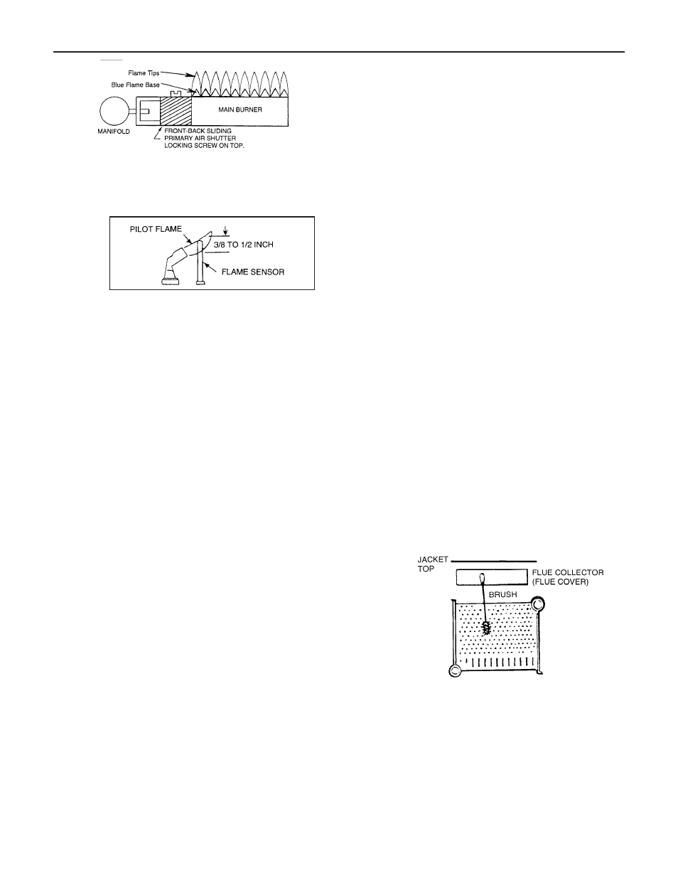
a. For proper operation the pilot should engulf the
thermocouple, powerpile generator or flame sen-
sor as shown below.
b. To adjust pilot, turn pilot flow adjustment screw
on valve clockwise or counterclockwise to give a
steady flame enveloping 3/8 to 1/2 inch of the tip
of the thermocouple, generator or flame sensor.
Note that turning the pilot adjust screw clockwise
will decrease the pilot flame.
c. Check safety shutdown of gas valve by following
procedure outlined "CARE" and "MAINTE-
NANCE" section, item IV-3 in this booklet.
CARE AND MAINTENANCE
WARNING: THE FLOW OF COMBUSTION AND VENTILAT-
ING AIR TO THE BOILER SHOULD NOT BE OBSTRUCTED.
This section must be brought to the attention of the owner by
the installer so that the owner can make the necessary
arrangements with a qualified service agency for the periodic
care and maintenance of this boiler. The installer must
inform the owner that the gas supplier can recommend a
number of qualified service agencies. The installer must also
inform the owner that the lack of proper care and mainte-
nance of this boiler and any fuel burning equipment may
result in a hazardous condition.
1. GENERAL MAINTENANCE (Refer also to Owner’s Infor-
mation Manual)
These operations are recommended to be performed at
regular intervals:
A. BOILER HEATING SURFACES: clean off all coatings
found.
B. BOILER CONTROLS: check contacts, settings, cor-
rect functioning.
C. PIPING: check piping and accessories for leaks.
D. CHIMNEY VENTING SYSTEM: check for obstructions
and leaks. If the boiler is vented horizontally through
the wall, the outside termination elbow and screen
should be checked for any debris blocking the opening
and cleaned as required.
E. BOILER ROOM AIR SUPPLY: check air vents for con-
tinued POSITIVE supply of air as required. Air needs
are greatest in cold weather. Air vents must be open
and free of obstruction.
F. WATER SYSTEM: check
1. System to be full of water, and pressure to remain
stable at correct setting on gauge.
2. Air-control system: noise and air binding in radiation
should not occur.
3. Water lines: slightest leaks should be corrected.
4. Low water cutoff, for operation (see instructions fur-
nished with unit).
II. WATER LEVEL CHECK DURING HEATING SEASON:
A. Check water pressure regularly and add water slowly
to system when needed.
If much water is added,
venting may be necessary.
B. Regular loss of water from water boiler system may
indicate either a system leak, or a faulty air control
system, or a faulty automatic fill valve.
III. ANNUAL INSPECTION AND CLEANING:
A. It is important that this boiler be inspected by a
competent serviceperson to help insure safe and
reliable operation.
B. Check for gas leaks from valve and gas piping to
burners and pilot. If leaks are found, repair or replace
as required.
C. This inspection should include:
1. Controls check. See SAFETY CHECK, IV.
2. Recheck of input gas rate to burners. See "Initial
Start" paragraph in "Operating Instructions" section.
3. Re-adjusting for best flame characteristics of main
flame and pilot(s).
See "Initial Start" paragraph in "Operating Instruc-
tions" section and see "Burner Adjustment" section.
4. Burner and boiler flue passage cleanliness:
BURNER AND FLUE CLEANING (see sketch). It is
suggested that paper be placed on burners to col-
lect any foreign material in cleaning flues.
5. Remove jacket top and flue cover. Remove inducer
assembly.
6. Use wire brush to clean flueways.
7. Replace flue cover and re-seal with furnace
cement. Replace jacket top. Remove and dispose
of paper and accumulated material. Replace
inducer assembly. To prolong life of motor, lubricate
with 6 drops of Anderol 465 annually.
8. If burner surfaces are not clean, or if uneven flame
indicates plugged burner ports, remove and
clean burners.
NOTE–TO REMOVE BURNERS:
1. Disconnect pilot at pilot mount, or disconnect
pilot gas line at gas valve, before removing burn-
ers next to pilot.
2. Lift burner and remove burner from orifice.
3. Clean and replace burners* and pilot. Adjust