Control features – SATO M5900RVe User Manual
Page 9
Unit 1: Introduction
SATO M5900RVe Operator Manual
PN 9001125A
Page 1-5
CONTROL FEATURES
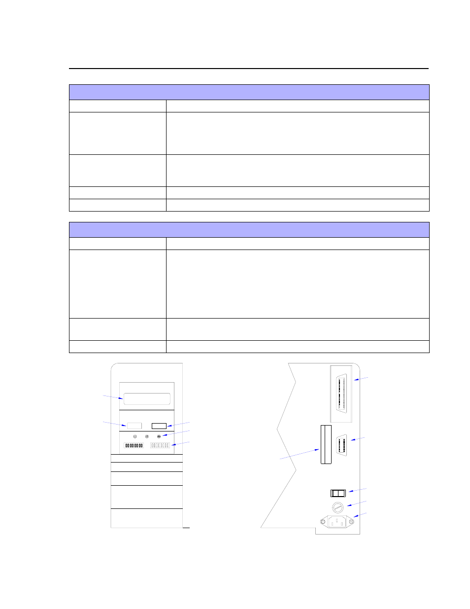
Figure 1-2, Switches, Indicators, and Connection Ports
SWITCHES
Power Switch
Two position on/off switch that controls power flow to the system.
Line Key
Toggles between on-line and off-line modes. When on-line, the
printer is ready to receive data from the host. Acts as a pause during
print by taking the printer off-line. Also used as a scroll-and-enter
interface for printer setup.
Feed Key
Feeds one blank label through the printer when off-line. When the
printer is on-line, another copy of the last label will be printed. Also
used as a scroll-and-enter interface for printer setup.
DSW2 & DSW3
Sets operational parameters of printer.
DSW1
To configure optional RS232 communication card. Located on card.
CONNECTION PORTS
AC Power Input
Connector permits 115V, 50/60 Hz supply via supplied cord.
Interface Port
Connector for interface harness. Must be connected for the printer to
be operational. Acceptable interface types are:
•
RS232C Serial I/F Module, DB-25
•
IEEE1284 Parallel I/F Module, AMP 57-40360
•
Universal Serial Bus Adapter
•
Ethernet 10/100 BaseT I/F Module
•
RS422/485 I/F Module, DB-9
Ext. Interface Port
Connector for external control of print cycle. Also supplies power for
optional accessories - AMP 57-60140
Memory Card Slot
Slot for the insertion of optional PCMCIA Memory Card
LCD DISPLAY
OFFSET
LINE
FEED
DSW3
LINE KEY
POWER SWITCH
DIP SWITCHES
POTENTIOMETERS
FEED KEY
PANEL COVER
REAR COVER
100V - 120V
FUSE T3.15A H 250V
EXT.
I/F
AC POWER INPUT
MAIN FUSE CONNECTION
EXT PORT
INTERFACE PORT
MEMORY CARD SLOT
POWER
DSW2
PITCH