Replacement procedures – SATO M5900RVe User Manual
Page 61
Unit 6: Maintenance
SATO M5900RVe Operator Manual
PN 9001125A
Page 6-3
REPLACEMENT PROCEDURES
The printer contains replaceable components and sub-assemblies. This chapter contains step-
by-step instructions for the removal and replacement of those primary components and sub-
assemblies that are subject to wear or damage.
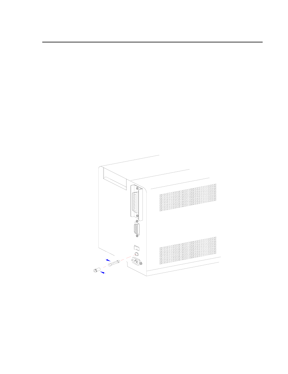
FUSE REPLACEMENT
The printer has three fuses; one is externally accessible and is wired to the power supply while
the other two are located internally and directly connected to the main circuit board.
1 Switch off the printer and disconnect the power supply cord.
2 Unscrew fuse cap (1, Figure 6-2) from the fuse connector located on the printer back side.
3 Withdraw cap (1) along with fuse (2) and inspect for damage.
4 Insert replacement fuse (2) into cap (1) and screw into the fuse connector.
5 Restore power.
Figure 6-2, Fuse Replacement
1
2