14 towing (optional hitch accessory), 15 adjusting the steering levers, 16 adjusting the height adjust pedal – Scag Power Equipment STT User Manual
Page 23: Figure 4-7 deck release lever, Figure 4-8 adjusting steering levers, Figure 4-9 height adjust pedal locations
19
Section 4
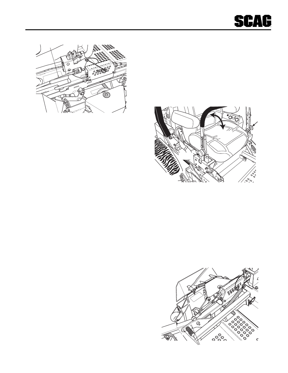
Figure 4-7 Deck Release Lever
4.14 Towing (optional hitch accessory)
1. Never allow children or others in or on towed
equipment.
2. Tow only with a machine that has a hitch designed
for towing. Do not attach towed equipment except
at the hitch point.
3. Follow manufacturer's recommendations for weight
limit for towed equipment. 250/lbs. maximum towing
weight.
4. Never tow on slopes. The weight of the towed
equipment may cause loss of traction and loss of
control.
5. Travel slowly and allow extra distance to stop.
6. Zero turning with a trailer attached could cause
damage to the trailer or mower.
C
U
TTIN
G
HEIGHT
6
5.5
5
4.5
4
3.5
3
2.5
2
1.5
1
48
15
43
390S0151-1
DECK RELEASE
LEVER
B. Rotate the steering lever forward or backward to
achieve the optimum operating position.
C. Tighten the tension knob and repeat on the
opposite side.
D. While in the operator's position, bring the steering
levers out of the neutral lock position and check
to make sure both levers are even before
operating.
Figure 4-8 Adjusting Steering Levers
TENSION
KNOB
TENSION
KNOB
ROTATE
LEVER
4.15 Adjusting the Steering Levers
1. Position the seat to the desired location.
2. While in the operator's position with out the engine
running, move both steering levers forward and
reverse to check for full function control and
comfort.
3. If adjustment of the steering levers is needed, use the
following instructions to adjust.
A. Loosen the tension knob on the lever assembly.
4.16 Adjusting the Height Adjust Pedal
1. Position the seat to the desired location.
2. While in the operator's position with out the engine
running, push down on the height adjust pedal to
check for full function control.
3. The height adjust pedal can be located in (3) three
different positions for operator comfort and control.
See Figure 4-9.
CU
TTIN
G
HEIGHT
6
5.5
5
4.5
4
3.5
3
2.5
2
1.5
1
48
15
43
390S0140-2
HEIGHT ADJUSTMENT PEDAL LOCATIONS
Figure 4-9 Height Adjust Pedal Locations