SMC Networks SpacePC 1232 Series User Manual
Page 63
63
63
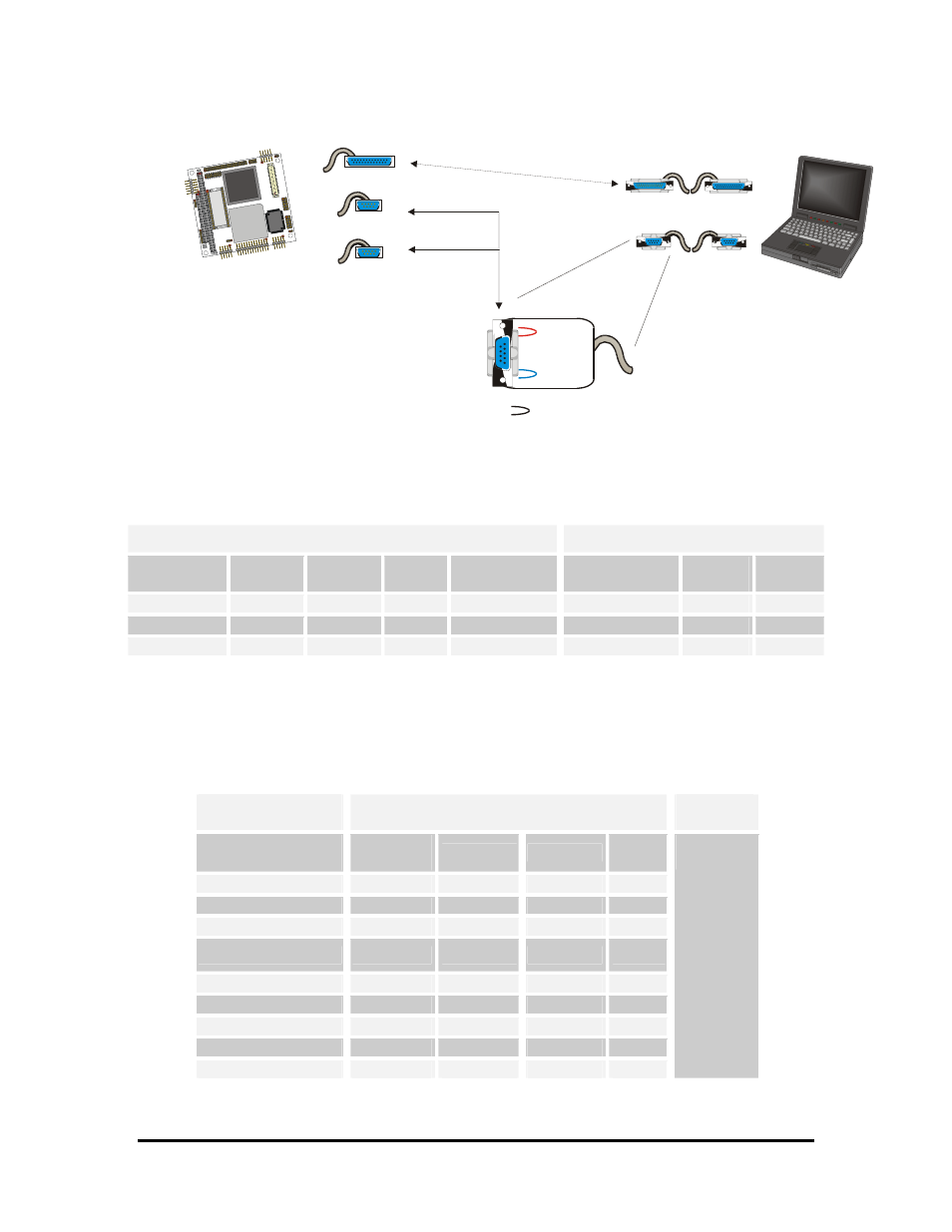
CPU
HOST COMPUTER
VP adjustment
(this end only)
or
RTS
CTS
DTR
RI
= short circuit
Short
(
) for using VP mode with SERIAL1
Short
(
) for using VP mode with SERIAL2
RTS1
CTS1
RTS2
CTS2
with or with
with or with
DTR1 RI1
DTR2 RI2
SERIAL PORT 1
PARALLEL PORT
SERIAL PORT 2
VP mode with Parallel DOESN’T NEED ANY SHORTs
Serial VP cable (*)
(*) This VP cables must be made observing the
connections explained in the following tables
Parallel VP cable (*)
Figure 23.
Completing the VP connection
Table 22.
Serial1 and 2 VP cable connections
PC/104 serial interface
HOST PC serial interface
J5 SERIAL1
PIN Nr.
DB25
PIN Nr.
DB9
PIN Nr.
Signal
Function
Signal
DB25
PIN Nr.
DB9
PIN Nr.
3
3
2
RX
Receive Data
TX
2
3
5
2
3
TX
Transmit data
RX
3
2
9, 10
7
5
GND
Signal Ground
GND
7
5
For VP mode connect
RTS1
with
CTS1
,
or
DTR1
with
RI1.
Pins not included in the table above are not connected
Table 23.
Parallel VP cable connections
From PC/104
Parallel connector
VP2000 Cable
To Host
Computer
J5 PARALLEL
PIN Nr.
DB25
PIN Nr.
Signal
Signal
DB25
PIN Nr.
1
1
STB#*
ACK#*
10
2
14
AFD#
BSY
11
3,5,7,9,11,13,15,17
2..9
PD#*
PD#*
2..9
6
16
INIT#*
PE
12
8
17
SLIN#*
SLCT
13
19
10
ACK#*
STB#*
1
21
11
BSY
AFD#
14
23
12
PE
INIT#*
16
25
13
SLCT
SLIN#*
17
Parallel
port