J11 auxiliary power connector – SMC Networks SpacePC 1232 Series User Manual
Page 32
32
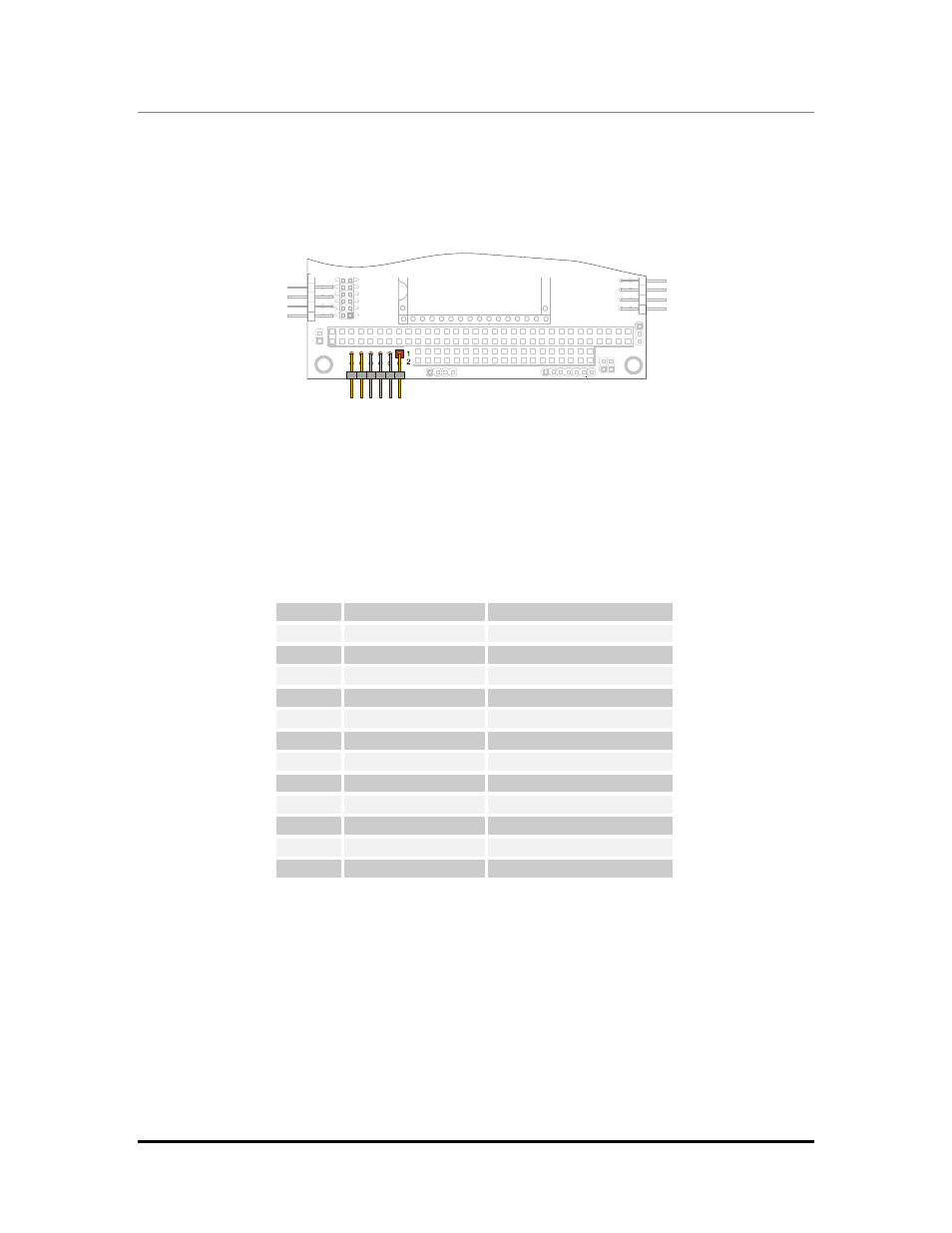
J11 Auxiliary Power Connector
One auxiliary connector is available on the SpacePC 1232 module. J11 is a 6x2 pin connector
with 2.54-mm step used to power the module in alternative to the PC/104 bus.
Auxiliary
Power
J11
Figure 18. J11 Connector layout
Check pinout and functions on the following table.
Table 17.
J11 Auxiliary Power Connector
Pin
Signal
Description
1
GND
Ground
2
VDD (+5VDC)
+5VDC signal
3
N.C.
Not connected
4
+12VDC
+12VDC signal
5
N.C.
Not connected
6
-12VDC
-12VDC signal
7
GND
Ground
8
VDD (+5VDC)
+5VDC signal
9
N.C.
Not connected
10
N.C.
Not connected
11
+5VSB
Always high (ATX only)
12
ATX ON
ATX Power on signal
The number and position of the pins that have to be connected depends on the Power Supply
model. Refer to the following topics in order to perform the right connections.
AT Power Supply
¾ Connect pin 1 and pin 7 to the ground signal of the AT Power Supply Unit.
¾ Connect pin 2 and pin 8 to the +5VDC source on the AT Power Supply Unit.
¾ Connect pin 4 to the +12VDC and pin 6 to the –12VDC sources on the AT Power Supply Unit
only if requested by other boards connected to the PC/104 ISA bus (see the following note).