Optional parallel interface pins and signal names, 167 appendix – Star Micronics SCP700 User Manual
Page 171
167
APPENDIX
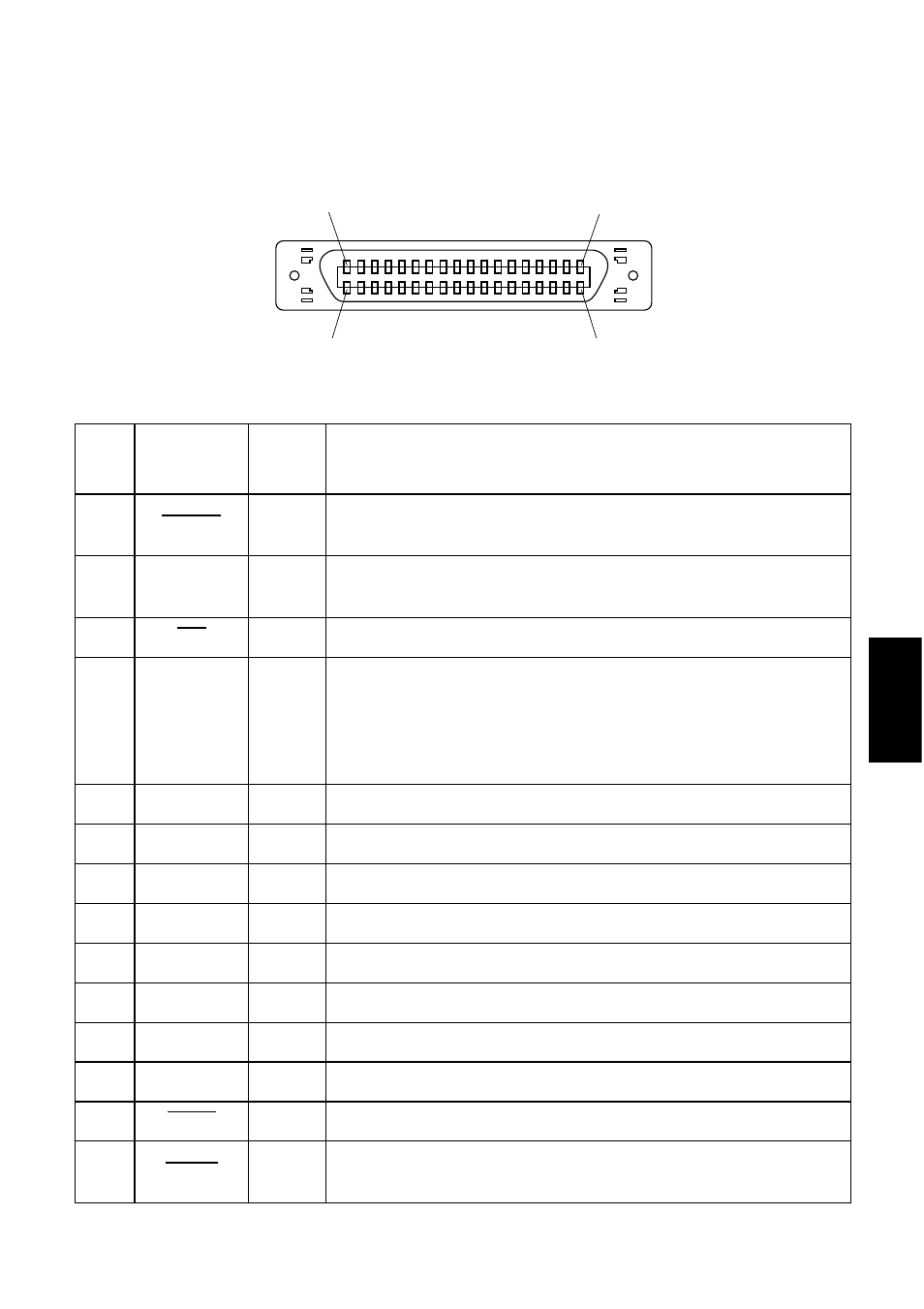
Optional parallel interface pins and signal names
Pin
No.
Signal Name
Direction
Function
1
STROBE
IN
Signals when data is ready to be read. Signal goes from HIGH to LOW (for at
least 0.5
µ
s) when data is available.
2 - 9
DATA 1 - 8
IN
Information on the first eight bits of parallel data. Each signal is HIGH for logical 1
and LOW for logical 0.
10
ACK
OUT
9
µ
s LOW pulse to acknowledge receipt of data
11
BUSY
OUT
Printer is ready to receive data when LOW. HIGH indicates one of the following
conditions.
• Data being entered
• Printer off line
• Error condition
12
PAPER OUT
OUT
Normally LOW, this signal goes HIGH when the printer is out of paper.
13
SELECTED
OUT
HIGH when the printer is on line
14
—
IN
This signal is not checked by printer.
15
N/C
—
Not connected
16
SIGNAL GND
—
Signal ground
17
CHASSIS GND
—
Chassis ground (isolated from logic ground)
18
+5VDC
—
+5V DC (max. 50mA)
19 - 30
GND
—
Twisted pair return signal ground level
31
RESET
IN
LOW when printer is reset to power-on defaults
32
ERROR
OUT
Normally HIGH, this signal goes LOW to signal that printing is disabled due to an
error condition.
(18)
(1)
(36)
(19)